DIY Ribbon transformer question

GroupDIY Audio Forum

Help Support GroupDIY Audio Forum:

This site may earn a commission from merchant affiliate links, including eBay, Amazon, and others.

Rossi

Well-known member
Joined
Dec 11, 2004
Messages
1,532
Location
Germany
I'm about to DIY a ribbon mic transformer. Basic idea is to re-wind the stock transformer of an inexpensive ribbon mic and see if it's worth the trouble.

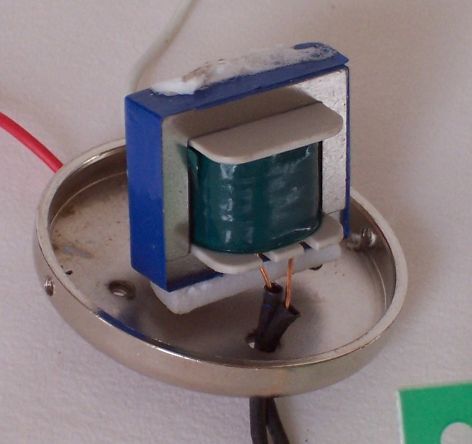
Usually transformers have some kind of inulation or screen between primary and secondary windings. The stock one, as far as I can tell, doen't have anything of that kind. There's only four wires coming out, none of which is attached to the metal can. (The metal can is connected to chassis/ground via its screws.)

Now, should I use some kind of insulation/screen between the windings and if so, what material should I use?
 
Screens are used in pwr transformers to keep crap from the line from getting into your circuit.

They do that, and also keep winding capacitance down on input transformers.

They lower capacitance on output transformers, but are not used for common mode noise issues, like the input.

What kind of turns ratio are we talking?
You might not need a screen.
Remember, you do not want a shorted turn that big, so insulate the ends from each other.
You can use copper foil or wire.

If you use wire, you wind a single layer, usually with fairly stiff wire, maybe #36-#38, in there somewhere, you leave one end free and attach the screen breakoutlead to the other end.

The two methods are used depending on the transformer design.

Let me see if I can dredge up the dope on how they differ, and when to use what.
 
If you do end up using copper foil, you might be able to find it in the gardening section of your local HW store (or German equivalent). They sell a nice adhesive backed foil here in the US to deter snails. I've used it to shield the control cavities of one of my guitars. A good sized 1" (25cm) roll is cheap compared the price charged by electronics places. It's pretty thin, but not so thin that you can't solder a wire to it with some care.

Cheers,
A P
 
I think I got mine at ACE, but OSH probably has it. I try to avoid BOB (Big Orange Box, a.k.a. Home Despot) when I can, too. Not always possible.

<edit> This stuff might be too thin/fragile for that 2503 external wrap. better check it.
 
Thanks guys! The original turns ratio is around 1:45. The resulting output impedance is pretty high for a mic, around 800 ohms. So I would go for a lesser ratio, say 1:30 or go even higher and add some active electronics. Lundahl has a 1:110 transformer for active ribbon mics. Now, I don't really expect to DIY a usable transformer like that. But then again, you never know until you try :roll:
 
Well, if you have a one turn pri, getting a 1:100 is no bid deal.
I think the pri turns are kept low because

a) the mic wants to push current, not voltage, thru the pri.
The less dcr, the better.
b) when building a 1:100 or thereabouts, you have to keep the turns down otherwise the capacitance goes out of sight in a hurry.

So a mic transformer is really kind of a curent transformer.
Current to voltage.

How many pri turns again?
What core?

cj
 
As I'm using the stock transformer core, I have no idea what material they used. Some kind of metal, not shiny. :? I havn't yet taken it apart. The stock transformer isn't stellar, but it's usable. My plan is to use a different bobbin of the same size, so I can rebuild the original transformer, if my experiments fail.

The transformer is pretty small. The bobbin must be about 10 or 12 mm wide. The thickest copper wire I could find was 1mm. So there would be about 10 windings for a whole layer. I should have at least one layer, no? Maybe I could double the wire, using the two wires in parallel. That way I would have about 5 windings, effectively. Then some copper foil - if needed - and then use whatever space is left for the secondary. I have 0.1 and 0.3 mm for that. Not yet shure what to use. For a 100+ ratio I may have to go for the thinner wire.
 
Edit: Just had another look at my photos (I don't have the transformer in front of me). The material is indeed a little shiny. Perhaps you can tell what it is:

stocktrans1.jpg
 
So my dream of world domination actually comes true?

Does my above plan sound reasonable (apart from world domination) and should I use copper foil as insulation or is it unlikely to make a difference in this application?
 
Try it without a screen first.
That way, if it works with low noise and good bandwidth, you save leakage inductance.
That layer of copper, since it is not part of the actual transformer windings, increases leakage.

If you look at a xfmr window, anywhere you see air or daylight, that is leakage.

Try a simple pri-sec test winding, like the Shure SM 57.

But first, see how many turns of the small wire you can get on the bobbin.
Then subtract a few turns, divide by your desired truns ratio, anbd then wind the pri fisrt.

If you have no room left for all the sec turns, no big deal.
So what if the ratio is 1:99, or whatever.
 
[quote author="Rossi"]Thanks guys! The original turns ratio is around 1:45. The resulting output impedance is pretty high for a mic, around 800 ohms.[/quote]

What is the ribbon's impedance (or DCR for that matter)? To measure it correctly you have to put it on bridge.

I am not sure if you will improve things dramatically with rewinding the thingy unless your goal to lower the ratio. The ones I saw (even the cheapest) always interleave sec-pri-sec, so not much to gain in this respect. In any case, the core material will be the main factor.

You will need to look at the pri-sec coupling, which can be quite poor for EI. If you calculate it as 1:30, in reality you might get something like even 1:20, so need to compensate for that.

I never actually had good results with EI for ribbons and found the UI works much better. Find a small UI or D (or even L) core (80Ni if you can), make 8-10 pri turns on each bobbin and then parallel them. The sec calculate and connect in series. For pri 1mm wire looks good. You don't need a screen, instead, use that space for thickest sec, you can fit.
 
I guess I'll just try and see what happens.

DCR of the ribbon as best as I can tell is about 0.3 to 0.4 ohms, measured with a (decent) digital voltmeter, the ribbon unconnected. Impedance of the whole mic was computed via impedance loss on a variable impedance preamp.Pretty much the only use I have for a variable impedance input, acutally :wink: Without even using any math I can tell that the mic's impedance is above 600 ohms. The pre is supposed to be 5 dB louder in its 600 ohms setting. (I suspect it's actually 6 dB and 500 ohms, for that would be parallel/series switching of the primary windings). Anyway, the mic is louder in the 2000 ohms setting, so impedance loss is greater than the extra gain.

Anyway, given the high step up ratio and the simple design, the stock transformer doesen't perform so bad. The primaries could be thicker wire, though, and the DCR of the secondary looks high to me at about 150 ohms. No? I think there's only one primary and one secondary.

Another thing I've noticed is that the wires to the ribbon are thinner than on some other ribbons I've seen. The material doesn't look like copper. I'm thinking about using fatter copper wire to reduce "dead" DCR a bit. But there's a plastic part on the other side of the ribbon clamp, so it may not be easy to solder without smoking that plastic part in the process. So I'm not sure it's worth the trouble. Do you have any experience with upgrading the wires to the ribbon?
 
[quote author="Rossi"]I'm about to DIY a ribbon mic transformer. Basic idea is to re-wind the stock transformer of an inexpensive ribbon mic and see if it's worth the trouble. [/quote]
Hi Rossi,

Just curious, is it any of those Thomann ribbons perhaps ?

Bye,

Peter
 

Latest posts

Back
Top