8 Channel, 3U NEVE 1073 completed

GroupDIY Audio Forum

Help Support GroupDIY Audio Forum:

This site may earn a commission from merchant affiliate links, including eBay, Amazon, and others.
In my continuing saga of getting Channel 1 to work like Channel 2 ...

I have visually compared and scrutinized both channels.  They are physically the same in every way that I can see.  Next, I checked transistor voltages against madriaanse's voltage table:

103ivyh.png


Here's what I got for both of my Channels (Rail Voltage: +24.0V):

Channel 1
Collector -Base -Emitter
TR1  23.600
TR2  24.023.623.1
TR3  24.000
TR4  3.82.31.8
TR5  12.33.83.2
TR6  20.712.311.6


Channel 2
Collector -Base -Emitter
TR1  4.30.80.3
TR2  22.34.33.7
TR3  22.33.73.1
TR4  3.82.31.8
TR5  12.23.83.2
TR6  20.712.211.6


Channel 2 looks good, but something is clearly going on with TR1,2,and 3 on Channel 1.  My next step will be to replace these transistors.  I hope that solves it.

I'm posting this here for two reasons. Primarily, because I have learned so much by reading similar troubleshooting posts from other members.  Maybe this can help someone else down the road.  Secondly, in case there are any suggestions of where to start or what to try replacing, or (better yet) an explanation of the voltage readings that I'm getting on Channel 1.


 
TR2 emitter should be the same voltage as TR3 base - they are directly connected. Have you tried re-heating the solder joints? Also, the 68K resistor is really a 68K and not a 6K8, right? Is the 47R resistor underneath 2N3055 damaged?

M.
 
Yep, as usual, it was something simple and stupid  :-[
Before replacing the transistors, I re-flowed them.  I think may have been the Base and/or Emitter of the 2N3055 that was the culprit.  All voltages look good.  Bias set.  Going to put it through it's paces at the studio later today. 

Thanks for the help!

madriaanse said:
TR2 emitter should be the same voltage as TR3 base - they are directly connected. Have you tried re-heating the solder joints? Also, the 68K resistor is really a 68K and not a 6K8, right? Is the 47R resistor underneath 2N3055 damaged?

M.
 
sr1200 said:
I have a channel that is making an intermittant spitting/static sound.  Should I just replace the caps on the board?

That would be my guess after verifying the PSU is clean. You could use a scope to see from which stage the crackle originates and start with those caps. Also, reheating solder joints can fix crackle if there's an intermittent connection.

M.
 
Martin, Thanks for the reply :) This is a 2ch unit i built for a friend of mine.  Only one of the 2 are doing it, so im ASSuming that the PS isn't the culprit.  Someone had mentioned that the tantalums are sometimes to blame for this kind of thing... i would think that any of those really delicate poly caps could be to blame as well.
 
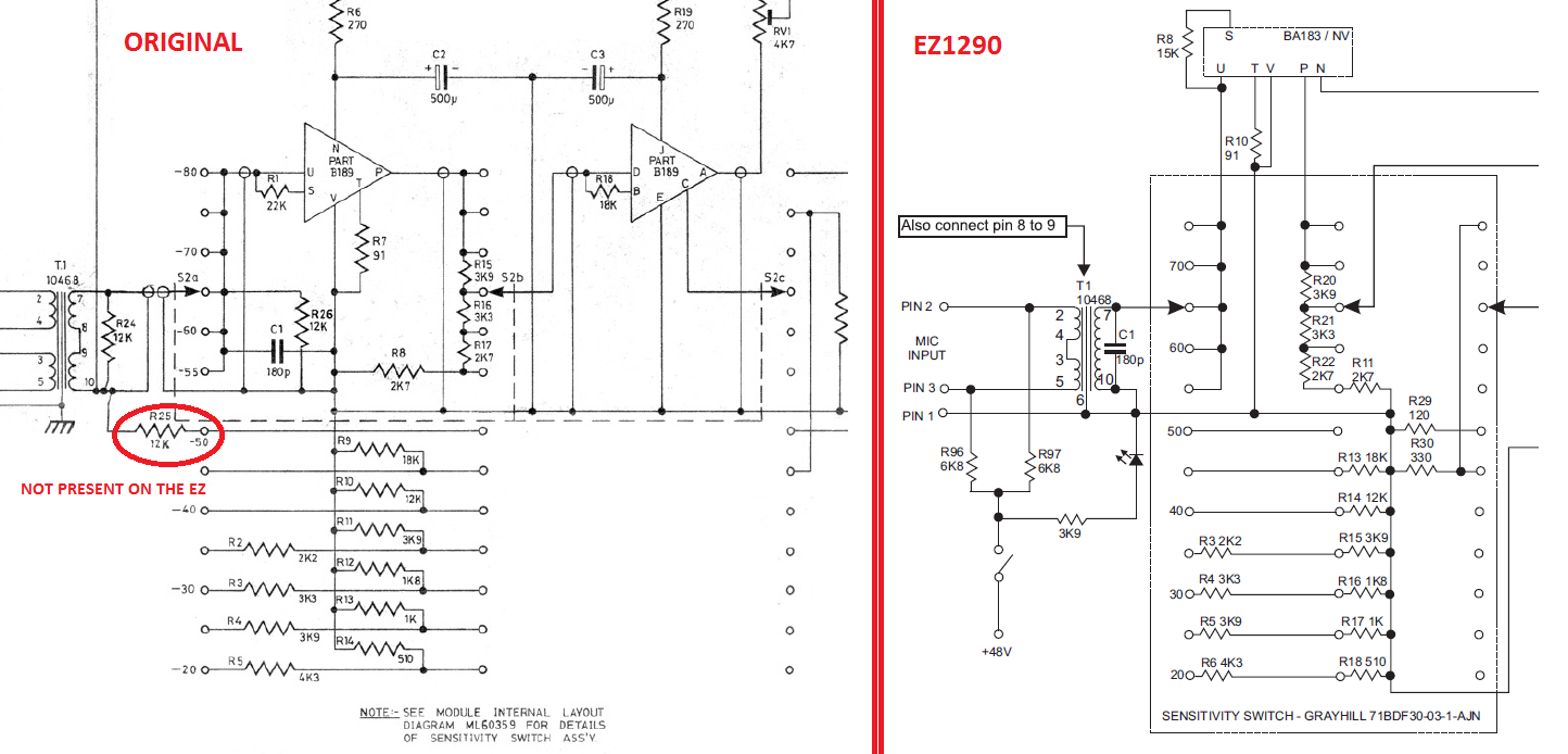
Hmmm. It seems the EZ1290 is missing a 12K resistor to ground on the first deck @50dB position.

I dont own the board so I am just referencing the schematic on the assembly guide PDF.

bgJkzX8.png


Is this a known issue? Am I missing something?

Also, whats up with the 180p cap? It seems it should only be used when at 55dB and above.

EDIT: what about R24 and R26?

It seems the EZ is based on the 1073 schematic and not on the 1290. Why the difference?
 
I have a question. I built 4 of these pres a while back and added an impedance selector switch, but can't remember what position is 1200ohms and what position is 300 ohms. Can I crack the case and measure impedance off the input transformer?

How can I measure input impedance?
 
Can anyone who added a impedance switch tell me if there 300 ohm position results in a louder and brighter signal? This seems to be the case with mine, using a Miktek CV4 tube condenser with an output impedance of 200 ohms.
 
@indiehouse - No, because it depends on the mic thats plugged into it.  For instance, my u87 clone sounds more open in the 300ohm, my shure KSM44 sounds more open in the 1200 ohm setting.  Unless there's a technical reason for one impedance over the other, just use your ears and go with what sounds better.  I always flip the switch before tracking just to see if there's a tonal difference (usually is), and go with the better, couldn't tell you if i had it on 300 or 1200 while im doing it though.
 
After doing a lot of research on electrical circuits for this project.  It's my understanding that impedance has to do with signal power transfer between different circuits.  In this case the AC to DC of the mic circuit to the preamp circuit.  I've read that an ideal ratio is 1:5 or greater.  The mic impedance being a factor of 1 and the preamp input impedance having a headroom of 5x or more greater.  A lot of mics have their impedance listed on their spec sheets.  Most mics that I've seen are 50ohms or 150ohms.  Like sr1200 said, without knowing which setting is which, just flip the switch and figure out what sounds better. 
 
EDIT :  operator error ... I posted in the wrong thread  ::)


  ... anyway , I used the fivefish  2448 PSU with the Avel Lindberg #Y236205 - 50VA , 2 x 22vac Sec. @ 1.14 each for 2 channels
 
Thanks!  I am doing a two channel build.  Seems Antekinc is out of 24v 50va unfortunately. 

@Audiophreak: What psu did you use?
Edit:  duh.. it say right above this you used a five fish.


Latest posts

Back
Top