Please help me analyze this circuit.

GroupDIY Audio Forum

Help Support GroupDIY Audio Forum:

This site may earn a commission from merchant affiliate links, including eBay, Amazon, and others.

tomelectro

Well-known member
Joined
Mar 28, 2006
Messages
100
Location
Los Angeles
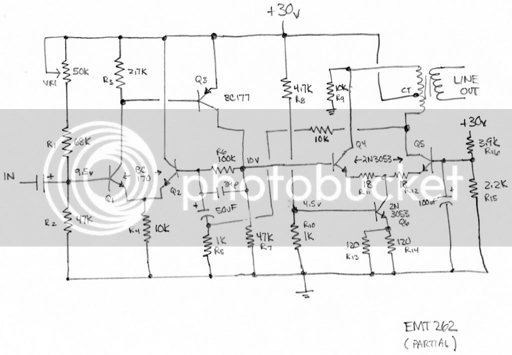
So I had to repair the electronics for an EMT plate reverb - the repair was easy enough (bad 2N3053), but I got a little stumped when trying to analyze the circuit. I figured the tail current in the differential input pair (through R4) should be about .9mA, so I would expect 1/2 of that to flow through Q1 and half through Q2. But the base-emitter junction of Q3 is anchoring the collector of Q1 one Vbe drop below Vcc (30v), which would result in about .22mA through R3 (2.7K), and therefore Q1. Is that correct? If so, where does the rest of the tail current go - through Q2?

The output stage looks interesting to me too. Would it be fair to say this is a differential pair acting as a class-A push-pull driver stage (Q4,Q5)?

Thanks for any comments-
Tom


EMT262.jpg
 
[quote author="tomelectro"] so I would expect 1/2 of that to flow through Q1 and half through Q2.[/quote]
Hi,

The base-voltages of the first diff-pair reflect the unequal collector-currents: 9.5 & 10 V, so the currents 'can' (or actually must) indeed be different.

Regards,

Peter
 
Peter, thanks for the reply.

I measured the base of Q2 and it is also sitting around 9.5 volts. I figured the drop as 5uA of base current through the 100k resistor. I was hoping that the base current would give me some ballpark insight on the collector current, but the figures for h(fe) I found for the BC170 ranged from 35 to 600 :roll: . I've been rounding my measurements to the nearest 10th volt, though. Maybe I should pull it back out and measure the difference base to base. I guess there really is no place else for the current to go except Q2. I thought (with my limited knowledge :oops: ) that the idea of a long-tail pair was to split the current evenly. Are there advantages/disadvantages to this scheme?
 
Pretty straightforward... q1 & q2 LTP, q3 gain stage q4 & q5 output drivers.

r6 provides DC feedback to establish nominal operating points while un-numbered 10k provides AC feedback path.

VR1 will trim input stage current density, which can be varied to balance input LTP but this looks like it will probably vary with temp, so perhaps it's just there to trim for max output before clipping. If trim voltage too low output drive current reduced, if trim voltage too high output voltage swing compromised. Or not...

JR
 
I thought that the idea of a long-tail pair was to split the current evenly. Are there advantages/disadvantages to this scheme?
I don't htink there is any advantage of having the collector currents unbalanced. That's why we use current mirrors (or differential second stages) today.

Samuel
 
[quote author="tomelectro"]Peter, thanks for the reply.

I measured the base of Q2 and it is also sitting around 9.5 volts. I figured the drop as 5uA of base current through the 100k resistor. I was hoping that the base current would give me some ballpark insight on the collector current, but the figures for h(fe) I found for the BC170 ranged from 35 to 600 :roll: . I've been rounding my measurements to the nearest 10th volt, though. Maybe I should pull it back out and measure the difference base to base.[/quote]

Hi,

I ignored the voltage drop by Ib across R6 since Ic was already so low, but with a low hFE it needs indeed to be taken into account. Different collector-currents must go together with different base-voltages (assuming identical BJTs for the diff-pair). As you know small differences in the base-voltages will already give 'observable' differences in collector-currents.

Regards,

Peter
 
> I figured the tail current in the differential input pair (through R4) should be about .9mA, so I would expect 1/2 of that to flow through Q1 and half through Q2.

Why would you expect that? It seems like a good idea, but the electrons do what they do, not what's a Good Idea.

As you say: 0.9mA in tail, 0.22mA in R3 and thus in Q1, 0.9-0.22= 0.68mA in Q2.

1:3 difference in transistor currents. So? It's still better balance and drift than a single transistor.

> The base-voltages of the first diff-pair reflect the unequal collector-currents:

If the system is happy (or not very unhappy), the currents are the tail current and the R3 current needed to keep Q3 alive. That 10V scribble is a rough reading. For a perfect pair, the base voltages will wind up to be 30mV apart. For the imperfections of the time, another 30mV either way. This offset, and offset drift, is far less than a single transistor's 600mV offset and 2mV/C drift. The fact it could be better wasn't worth worrying about. It does not have to be great.

I tend to agree with John that you must trim VR so Q4 Q5 run equal current for low DC unbalance in the output transformer. Oytput is running say 60mA, you want 30mA per side, in 18 ohms that is 0.54V. Say you can accept a 10% unbalance: 3mA in 18 ohms is 54mV. The "poorly balanced" Q1 Q2 input is much more stable than that, after you trim-out the initial +/-30mV device offset and ~30mV unbalance. If you used a single input device, 25 deg C temperature shift would throw the Q4 Q5 pair more than 10% unbalanced and the output transformer bass performance would suffer.

2N3053 shouldn't die. Was the output shorted and driven hard?
 
[quote author="PRR"]This offset, and offset drift, is far less than a single transistor's 600mV offset and 2mV/C drift. The fact it could be better wasn't worth worrying about. It does not have to be great. [/quote]
In a book of which I can't find the title of right now, JLHood makes a nice transition from an amp without Q2 (so getting gain from a Sziklai-pair Q1 & Q3) to an amp with a diff-pair (by adding Q2 as a 'more convenient' entry for feedback.
Looking at it in that way, it's clear that the addition of Q2 helps the already present two BJTs but it doesn't immediately trigger the usual 'hey we have a diff-pair so it must be in perfect balance'.

Regards,

Peter
 
Thanks for the replies! :sam:

Why would you expect that? It seems like a good idea, but the electrons do what they do, not what's a Good Idea.

I guess just because that's how I've seen it in the textbooks :oops: .

2N3053 shouldn't die. Was the output shorted and driven hard?

I'm not sure what happened to this thing, but Q5 (2n3053) was blown in both the L and R channels. No telling what this was patched to. I catch people around here patching equipment outputs together all the time.

Tom
 

Latest posts

Back
Top