Time to take apart the Fender Champion 600 (Pics)

GroupDIY Audio Forum

Help Support GroupDIY Audio Forum:

This site may earn a commission from merchant affiliate links, including eBay, Amazon, and others.

matta

Well-known member
Joined
Jan 11, 2005
Messages
1,640
Location
Cape Town, South Africa
Hey Guys,

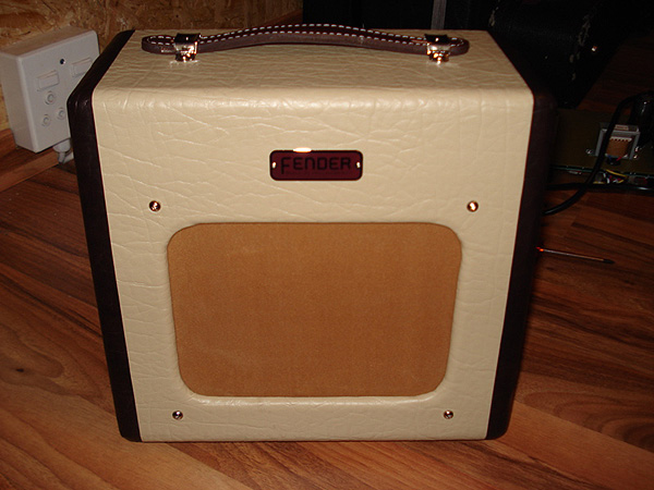
For the longest time I've wanted to build a little low wattage Valve/Tube amp for recording and had my sights set on building a little Fender Champ, the 5F1 version, but being on the butt end of Africa made sourcing parts difficult and fairly costly and so I abandoned the idea... until January '07 when Fender announced this little guy.

Champion_600.jpg


Not only did it look great, but sounded great (from clips I'd heard) and was a sleeper at the price (under $200!) Costs were kept down being built in China and I guess is Fenders answer to Epiphone's low cost Valve Jr.

I thought the worst that could/would happen is I buy it and it sucked but am left with killer chassis and cabinet to build my own Champ in.... I wasn't at all disappointed though!

The amp itself is pretty amazing, esp. for the price though I think would benefit greatly from upgrading the stock valves from the no name 'chinese jobbies' to a nice set of JJ Tesla's and replacing the cheap speaker with a Weber or Jensen which I plan to do in time.... also could drop a Hammond or Mercury output trafo...

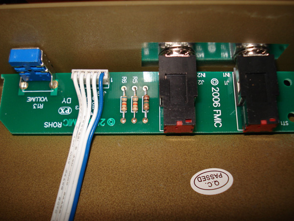
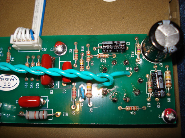
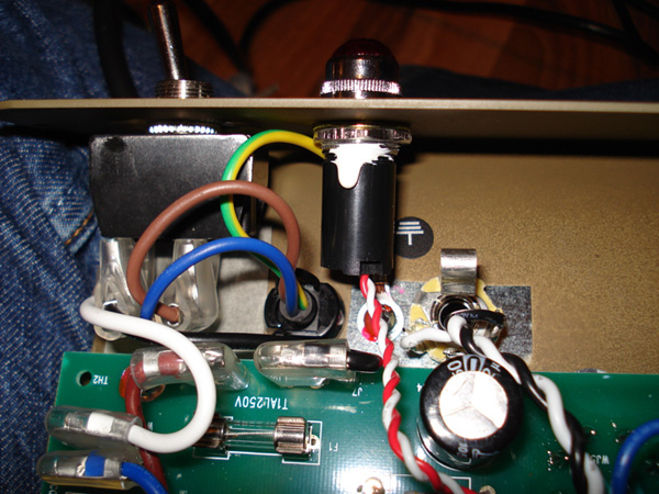
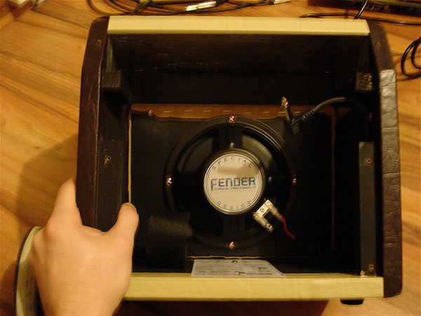
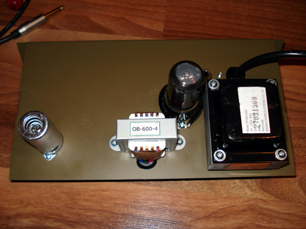
Being the inquisitive guy I am I rushed back after buying it and took it all apart, shot a few pics and then went about retracing the circuit... low and behold found it is isn't the old Champion circuit at all but a pretty much PART FOR PART clone of the 'Black Face' era Champ using the AA764 circuit!

Here are a few pics of the guts.

Champion_600_PCB2.jpg


Champion_600_PCB1.jpg


Champion_600_PCB3.jpg


Champion_600_PCB4.jpg


I've uploaded the SCHEMATIC with the redrawn values on it and it can be found here:

http://www.matt-allison.com/diy/fender/champion-600-schemo.gif

Where it differs from the original 'Black Face' is that it has a solid state power supply, (which I've not redrawn), the power transformer lacks a center tap but has the 2 x 100R virtual center tap trick to mimic it, it also has a fixed tone stack unlike the original Black Face that had separate Treble and Bass controls. It also features a custom built 6 inch speaker where the original had an 8 inch one.

Now I'm kind of new to Valves/Tubes and the only other piece I own is an LA-2A I built a few months ago so my understanding of valves and their inner workings is limited and I'm hoping those with more experience will try open this up for me and expound on a few things.

I'd like to investigate some mods one of which may be to remove the fixed tone stack and replace it with 2 small panel mounted pots and reclaim the TREBLE and BASS controls, the other may be to lift the tone stack all together, which I've read may increase the gain/output level.

What I am wondering about though as well is the choice or values of the resistors, in the original you had 2 x 250K pots with the Bass pot having a 15K to ground, now in this unit they are fixed at 75K but the 15K is now 180K! Why the huge jump?

It has quite a bit of hum on it which I'd like to reduce and I seem to recall Analogpackrat saying something about putting a cap and resistor before the output transformer to reduce it???

Also wondering why they added the extra 470R/1W resistor onto pin 4 of the 6V6? What is it's role there?

Thanks in advance for any suggestions or help.

Cheers

Matt
 
[quote author="matta"]I'd like to investigate some mods one of which may be to remove the fixed tone stack and replace it with 2 small panel mounted pots and reclaim the TREBLE and BASS controls, the other may be to lift the tone stack all together, which I've read may increase the gain/output level.

What I am wondering about though as well is the choice or values of the resistors, in the original you had 2 x 250K pots with the Bass pot having a 15K to ground, now in this unit they are fixed at 75K but the 15K is now 180K! Why he huge jump?[/quote]

Looks like a nice amp to have around :thumb:

Maybe they tweaked the tone-stack values to suit the speaker etc that they used and couldn't help arriving at 'weird' values ?
 
Matta, Very cool, thanks for the pics! Regarding the hum, it looks like the heater wires are sitting right on top of C8 and C9. Even though they are twisted, maybe there is still some leakage through the tone stack?

-Chris
 
They are boosting the mids with the 180K, leaving bass and treble at "nominal" settings.

If you ground the grid of the power tube (pin 5) and the hum is still there, then up the power supply filtering.

The 470 is to surpress oscillations on the 6V6, or fuse it when it shorts and hopefully save the pcb trace..
 
Matt,

Cool amp! Thanks for sharing.

Download the Tone Stack Calculator from the Duncan Amps website and you can simulate your current tone stack and then try mods in simulation.

I think Plexi's advice is right on in troubleshooting the hum. If you need to add PS components, they go between the rectification and C6. I wonder if that 2x 100 Ohm gnding is part of the hum problem...

I wonder why C10 is 250V?? (edit...meant to say 450V as Matt says in his schematic values!!)

If it were mine, I think I would add the Bass and Treble pots and then a master volume (1 meg audio taper) just behind C2.

Enjoy!
 
Would love to see pics of the whole chassis from both sides, including transformers orientation.
If you check out Bills Blues Junior page, there is some interesting info on the transformers placement, PT inducing hum in the OT.

Kåre
 
My .02c ... Lose the tone stack ..... Just swap decoupling caps until you get the balance of bass and treble you need .... if you want a bright switch ... just switch between different caps.... eg .02uf to a .01 or .001 ... whatever. You might be surprised how much better the thing sounds ....

And yup .... a good OT might thrill you ... You can always run out to an extension speaker you have around.....
 
A few things

For the hum

First you can try changing the first cap in the B+ to a known good cap brand. ESR matters there. I don't like to use a lot of uF in tube amps.

OR you could raise the fil center tap above ground.

Check the value of the fil resistors to make sure they are correct.

I would try different tubes before I did anything to the amp.

For tone

When I rebuilt a tube PA (SE one 6l6 and a 12ax7) I found I liked the amp better without the 470 ohm screen protection resistor. Next time I rebuild it I might try a 100 ohm

I would guess the fixed tone is to help out the 6 inch speaker.

Look for Roger's thread on his SE build
 
[quote author="Emperor-TK"]Matta, Very cool, thanks for the pics! Regarding the hum, it looks like the heater wires are sitting right on top of C8 and C9. Even though they are twisted, maybe there is still some leakage through the tone stack?[/quote]

Thanks Chris, will move em and see if it makes a difference, I think it might lie more in the PSU, but will try anything to reduce it.

[quote author="plexi"]They are boosting the mids with the 180K, leaving bass and treble at "nominal" settings.
If you ground the grid of the power tube (pin 5) and the hum is still there, then up the power supply filtering.

The 470 is to surpress oscillations on the 6V6, or fuse it when it shorts and hopefully save the pcb trace.[/quote]


Plexi, thanks for all that info, I downloaded the Duncan Tone Stack software and when I punch in those values the tone seems to even out more, than with the stock values.

Interesting about the 470 on the 6V6, it seems to be missing from the orginal schemo I found, was this something they only learned about later down the line? Tonally does this resistor have an effect sonically?


[quote author="SonsOfThunder"]I wonder why C10 is 250V??[/quote]

Nope it is 25V, not 250V.

[quote author="lydmann"]Would love to see pics of the whole chassis from both sides, including transformers orientation.[/quote]

Will shoot some over the weekend or on Monday when I'm back at the studio with my camera.

[quote author="Mikka"]And yup .... a good OT might thrill you ... You can always run out to an extension speaker you have around..... [/quote]

I thought about this for running it out into and external cabinet as the output trafo onboard is 4Ohms, I thought a multitap hammond might be more useful RE having an 8 or 16Ohm out as well on separate jack sockets.

[quote author="Gus"]A few things

For the hum

First you can try changing the first cap in the B+ to a known good cap brand. ESR matters there. I don't like to use a lot of uF in tube amps.

OR you could raise the fil center tap above ground.

Check the value of the fil resistors to make sure they are correct.

I would try different tubes before I did anything to the amp.

For tone

When I rebuilt a tube PA (SE one 6l6 and a 12ax7) I found I liked the amp better without the 470 ohm screen protection resistor. Next time I rebuild it I might try a 100 ohm

I would guess the fixed tone is to help out the 6 inch speaker.

Look for Roger's thread on his SE build[/quote]

Hey Gus,

Thanks as always for your masterful advice.

I will try and source a quality cap for all the lytics if possible, but def. In the B+ section, when you say you don't like a large value, do you feel the 22uF is a bit much, are your talking around 8uF like the older Champs?

The filament resistors seem to be correct, R15 and R16, both 100R

With regards to the 470 Oms screen when you said you liked it better without it do you mean sonically it sounded better? How so, smoother, softer? Just trying to get my head about the effect it has on things.

I notice if you drive the amp anything about 6-7 it can get a bit 'farty' as it craps out the little 6 inch speaker, as you say I'm guessing the tone is fixed to prevent you bossing the controls and killing it even earlier on... I need to build a cabinet for it or get a better/bigger speaker I think.

I have found Roger's thread, I'll go through it again.

I think the biggest issue first and foremost it to lower the hum, then replace the valves/tubes and check it out, in time add a multitap output trafo, maybe replace the 6 inch speaker with a better one and or build an external cabinet and only then decided what to do RE the tonestack controls.

Thanks again you all for your help!

Matt
 
Also for hum check the grounding connections. I have "fixed" amps by cleaning connections

"farting out" old fix, reduce C2 try .01uF or .0047uF etc film, ceramic, silver mica.......

The amp SEEMED to have more "punch" without the 470 ohm

A short story about a fender twin and why I care about ESR

Years ago
A friend recapped a fender twin with a common replacement cap brand. The amp had ghost notes they doubled the input B+ caps it still had ghost notes. The amp with the original caps did not have ghost notes. We were talking about this and I measured the orignal caps value ESR DA and leakage and the replacement caps. The old ones measured good but they did not look good. The replacements measured much higher in ESR and lower than marked in value

IIRC From measuring caps at 450 to 500VDC on a sencore lc102
OLDER atoms(saw a thread at the twreck page about new atoms they might have changed them)
about 1.5 ohms or lower ESR per 22uf

the old, used, original caps in the fender were about the same readings as the atoms

The replacements 5 to 10 ohms ESR at 500VDC rating and 22uf

They then installed atoms and the ghost notes went away and amp sounded good.

The first two caps in the B+ supply of a power amp seem to me to be the most important.

The cap size is a TASTE issue the smaller you go the more you can collapse the power supply voltage with volume but you can have hum problems. Can be good or bad.

From years of measuring Al electros. Old ones would often be > than marked value 22uf might be 30uf or so. New ones often measure very close to the marked value.

Google the motherboard cap failure issue. I still see motherboards with this issue. So now I don't trust Al caps until I measure them.
 
Gus, that is an interesting story about the Twin and electrolytics...I have a Blackface super I'm working on and it is sonically "dead", just sounds like crap to me. It has been recapped with cheaper Illinois Caps, I'll try some TVA's in the main supply and see if that improves the sound.

The guy is going nuts because his Silverface sounds better...thanks for the tip.

I always liked the tweed Champ better than blackface, simpler, sounded better and more pure to me...never did like the scooped tone stack sound of later fender amps.

Brown Deluxe beefed up with a greenback, best amp Fender ever made.
 
>>>Nope it is 25V, not 250V.
Sorry Matt, meant to say 450V...that is what your schem shows there. :sad:

I am excited to see what you do with this amp.

wrt what Gus is saying about ESR, it is amazing to see how changes in cap ESR can effect power supply behavior in all kinds of circuits...sometimes even when reducing the cap value!

Duncan's TSC is da bomb ain't it? I especially like that they have included the old BMPi tone control ckt.

Peace!
 
Matt,

Take a look at this thread for a summary of what I did to my SF VC. The farting out may be blocking distortion. I had that problem and tamed it with a smallish grid resistor on the second triode. You could have a switch for reduced negative feedback if you want more of a tweed tone (put a 22k in parallel with the existing 2k7, but switch the 2k7 using a spst at one end). You could also switch out the tone stack.

Anyway, I'm 90% sure that your hum/buzz problem is simply caused by poor filtering at the power tube plates (which are fed via the output transformer primary in SE amps). Break the connection between the rectifier and the junction of the first existing filter cap/1k/output transformer and insert a 10uF or 10uF to ground followed by a 300R to 1k power resistor (figure wattage based on P = VI where I is somewhere around 15-20mA) which connects back into the main B+ where you made the initial cut.

If you still have hum after that, mess with the heater wiring. I doubt that will help much. My VC had really crappy heater wiring--one side of the 6V tap tied to chassis and a single sided heater wiring scheme with ties to chassis at each tube. I redid this with the standard twisted feed with a false center tap referenced to the 6V6 cathode and it made very little difference. The PSU filtering did the trick.

Play it through a big cabinet before trying a new output transformer. 8 ohms won't hurt anything. I've been using an 8 ohm 2x12 cabinet with my VC a lot. It pumps plenty of bass even with the junky little output transformer.

A P

p.s. Don't forget to read Roger Foote's thread on his SE amp build...
 
Is the hum 50Hz or 100 Hz? If it's 50Hz, look for ground problems, inductive coupling from power to output transformer or filament wires to signal, stuff like that. If 100Hz, look for inadequate supply filtering.

These aren't guaranteed (ground problems occasionally show up as 100Hz as well) but good starting points.

[Edited to take notice that you're in a 50Hz country, not 60Hz.]

Peace,
Paul
 
My bad re: the tone stack ... I looked at the schematic not the photo ...The tone is probably fixed 'cause with these little amps you don't need a tone control ... and they suck so much life and gain ....

Re: those 100 ohm resistors on the heater circuit ... might help if they're run to earth from the first valve ... is that where they are?

Is the heater circuit positive biased? That's another cool option ...

After that .. if it still hums .... you probably need more filtering on the B+ as mentioned by Gus .....

Sorry if I've repeated others here ... I wanted to feel useful this morning... :green:
 
Hi Guys,

As promised here are a couple shots of the cabinet and chassis.

I've been playing more with the amp today and enjoying it, the hum is a small bug bear, but I've heard worse. I think the first 'mod' will be better valves/tubes and then see where to go from there.

Champion_Cabinet.jpg


Champion_Cabinet2.jpg


Champion_Chassis.jpg


I was thinking worst case I could remove the PCB and still be left with a great cabinet, chassis, speaker and power/output trafo circuits and build the much loved 5F1 P2P inside the chassis.

Charlie that cap is 25uF/450V as you see it but it is C3, not C10 as you stated previously, hence my confusion.

Cheers

Matt
 
Matt,

My mistake. Okay, its a picky thing, but your schematic has C4 marked as 25u/250V instead of C3 as you said in the last post. I still think it must be an error on their part as none of those cath bypass caps need to be any higher than 25V.

Man, that thing is like an amp...only a lot smaller! :cool: HAHA! Really its a cute little thing.

Peace!
 
it hums?
its single ended?
welcome to Earth!


the main thing that influences the sound of this amp are the tubes.
why?
well, what else is there?
some carbon from somebody's #2 pencil, a few pieces of rynolds aluminun, (sp and i don't care) and a weird, non stock spk (orig was 3.2 ohms) and non stock OPT.

rip out the pcb and do it point to point for a more three dimesional sound.
(the board changes the capacitance>sound-co planer as opposed to x y AND z.
 
Excellent article followed by lots of good advice. Apologies for going back on the earlier discussions but I have traced and drawn up the circuit schematic below, hopefully answering all the queries about resistor and capacitor numbers. The circuit also shows 4 mods I did after replacing the 12AX7 and 6V6, at least two of them have been discussed already.

Champion600_partial_schematic.jpg


The circuit is based on the AA764 design but with a fixed tone stack and I have shown below the stock EQ curve compared to cutting R19's link to earth:

Champion600_tone_stack_with_text.jpg


Hope this is helpful.
 
Back
Top