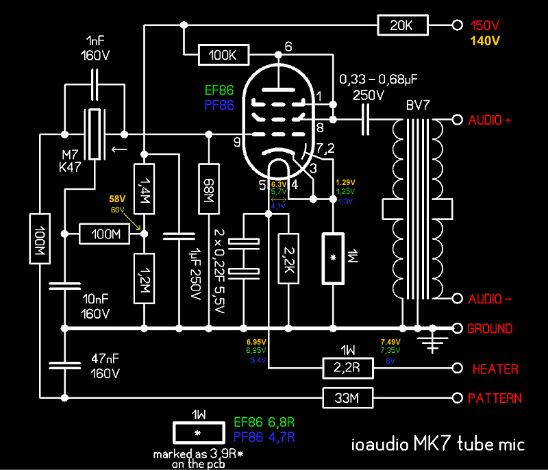
On the attached schematic is the output cap is set to 0.33-0.68uF. I settled initially on 0.47uF but noticed there is a sharp drop off at 20Hz, like 20dB so I increased it to 0.68uF and it opened it up a bit, but still lacking in the low end a bit, which would be nice on kick drum/bass etc.
Is it safe to go even larger, or are there other places to tweak the circuit that are a better option?


")