Passive Spring Reverb?

GroupDIY Audio Forum

Help Support GroupDIY Audio Forum:

This site may earn a commission from merchant affiliate links, including eBay, Amazon, and others.

plumsolly

Well-known member
Joined
Nov 3, 2007
Messages
969
Location
Denver, Colorado
I have a hankering for spring reverb and nothing else will do. My plan thus far is to put transformers on either end of an accutronics reverb tank, drive it with the effect send line drivers from my console (these are a ne5534 followed by a transistor pair pushing a 150:600 transformer), and use mic pres for makeup gain. The basic idea is the same as the coolsprings by zerotronics seen here http://zerotronics.com/coolsprings/index.html
He lists the input impedance as 800 ohms and the output impedance as 60 ohms. I'm assuming that the reverb tank is 800 ohms in with a 1:1 transformer in front, and 600 ohms out with a 3:1 stepdown transformer after it. Does this sound right?  the reverb tank would be this here http://www.accutronicsreverb.com/Type9.htm. This is from the accutronics website: "Since the output transducer is also essentially inductive, output impedance increases with frequency. Amplifier input impedance should be high enough to prevent premature roll off in the frequency range of interest (i.e., the 10,000 ohm coil appears as 60,000 ohm source at 6kHz)." 
Does this all sound right? Will the reverb tank(s) be able to drive that stepdown transformer O.K.? Is there anything else I should be thinking about? –
Thanks, Ben
 
If you order a tank with a Type F input transducer and a Type A output transducer, you could probably drive it directly from an aux send and hook the output up to a mic channel. Try it.

Just be sure to observe correct practices for connecting balanced to unbalanced equipment.
 
If you find, you need more drive, you could try a headphone amp between the send and the reverb tank input.
 
Thanks for the input. Rossi - I'm expecting to be able to drive it pretty well with my console - If the effect sends dont have enough juice, I can set up sends in the box and assign them to a couple of channels on the console and drive it with the direct outs - they have tons of gain, especially with the driver stage on the output and the step-up transformers. Dave -will 600 ohms out at 1kcps be ok with the rising impedance with frequency? My console's manual lists the mic inputs as 2k ohms actual impedance and 20 to 200 as the acceptable range (its an auditronics 110).The line inputs are listed as 10,000k ohms actual and 600 to 1200 acceptable. It just pads the line input before the transformer. thanks again, Ben
 
It's not so much gain that you need to drive a reverb tank as a low output impedance, so a step up transformer won't help. Hence my suggestion of a headphone amp. 2k input impedance may be a bit lowish for best results. You could try a guitar pedal (fed into the line input) as an impedance converter. A stomp box EQ would do fine, as it presents a high input impedance of 500k-1M and you can also use it to shape the reverb sound. Most guitar pedals will work as a impedance converter even when switched off.
 
Check out
http://www.generalguitargadgets.com/index.php?option=com_content&task=view&id=43&Itemid=26
and
http://sound.westhost.com/project34.htm

Both of these deal with spring reverb drivers and receivers plus they dont look too hard to build.
 
thanks for the links, Mylithra. Rossi - how about a fender champ type amp as a driver. I just built one, and I have another silvertone amp that is one 6v6 output. these are meant to drive 4 ohm speakers - If I turned the volume down, you think it would work well? - Ben
 
Rossi said:
2k input impedance may be a bit lowish for best results.

Read the description of the line drivers in his console. They should be able to drive 2k.
The rising impedance vs. frequency of the reverb transducers is not a problem, since you generally want some LF rolloff going into the reverb, anyway.
I'd try the simple way first and take it from there.
 
NewYorkDave said:
Rossi said:
2k input impedance may be a bit lowish for best results.

Read the description of the line drivers in his console. They should be able to drive 2k.
The rising impedance vs. frequency of the reverb transducers is not a problem, since you generally want some LF rolloff going into the reverb, anyway.
I'd try the simple way first and take it from there.

I agree that it's best to just try and see. I'm not sure about the line drivers; without the step up transformer they should work fine, but with the step-up, output impedance increases. Nontheless it's easiest to just try and see.

I think you're wrong re the transducer thing, though. Here's what accutronics say:
"Since the output transducer is also essentially inductive, output impedance increases with frequency. Amplifier input impedance should be high enough to prevent premature roll off in the frequency range of interest (i.e., the 10,000 ohm coil appears as 60,000 ohm source at 6kHz)."

Now, if the output impedance rises with frequency, a lowish input impedance on the receiver side (2k Mic input) should result in HF roll-off, not LF roll-off. While some bass roll of would be a good thing, high frequency roll off may not be what you want, particularly if you like that shattery twany spring reverb sound.

I don't know about the champ as a reverb driver, may be overkill and I'm not sure the driver coil could withstand that much juice. As Dave recommends: Just try and see. If it doesn't work out as expected, have a look at the circuits Gus pointed at; they're easy enough to build. The headphone amp was merely a suggestion if you have stuff like that lying around, also the guitar pedal as impedance converter.
 
Rossi, my comment was concerning the drive side of the reverb, not the recovery side. But yes, it may be necessary to go above a 2K load on the output transducer. I'd try it as-is first and find out how it sounds. This is, after all, a "special effect."

By the way, you can experiment with the effects of parallel resonance by adding a small capacitance across the reverb tank output. I did this in a tube reverb unit years ago, with good results.
 
Well.. Check this out:
http://www.schematicheaven.com/fenderamps/reverb_6g15_schem.pdf

The output tranformer is different from a champ but the circuit isnt all that different on the driver side.
The 6K6GT is an output tube though I dont know the wattage right off the top of my head but I beleve its under 5. Weber has this in a kit but I think they use the 6V6GT tube.

It all depends on what the pan calls for. Should have a model on it that will tell you what the input impedence is.

 
I just looked at this thread and am noticing that it's getting pretty off topic... I thought this was about PASSIVE.
I'll just place the info here so I can reasearch a bit more when I have time, meanwhile anyone out there that wants to chime in: go nuts.
Inside the unit are four Accutronics® type 9 reverbs.

Physically, they are bolted together in clamshell pairs and surrounded on all six sides (and held in place snugly) by a resilient foam rubber lining. The padding is double-thick in front to provide extra protection when the unit is kicked.

Electrically, they are surrounded by impedance-matching circuitry using high-quality mil-spec audio transformers. The internal wiring is balanced and the reverb pairs are connected in a hum-bucking arrangement to minimize external hum pickup. Chassis ground is connected to pin 1 of the input connector. For each output, pin 1 is connected only to the internal shielding of the output circuitry.
What's interesting is that the zerotronic unit has 4 tanks and splits 1 in to 2 outputs.
So assuming that the units inside are part numbered something like this: (this is the highest input lowest output impedence version made)
type 9      F                             A                    (1,2,3)                      (A,B,C,D)                           1           A
           1925ohm input         600ohm output    (s,m,l)decay time       connector options(x,x,x,x)  Lock     horizontal mounting

there's an input transformer and probably straight signal split from there to the 4 tanks
then 2 tanks are summed into each of the 2 output transformers to 2 outs...

Seems like the parts are pretty easy to sort out for someone with some knowledge of impedence and reactance calculation. (that wouldn't be me though- at least not off the top of my head...)  one just needs to find an ideal input transformer for running into the tank, values for a summing network and 2 output transformers and the skilz to wire those in a humbucking arrangement.
Sleeper

 
The ares I am still confused about are:

1. In the zerotronics system, input impedance is listed as 800 ohms - how are the four tanks connected to get this input Z? why wouldn't one just connect four 1925 ohm-input tanks together in series to get an input Z of ~8k? Does this have something to do with the "humbucking arrangement"?

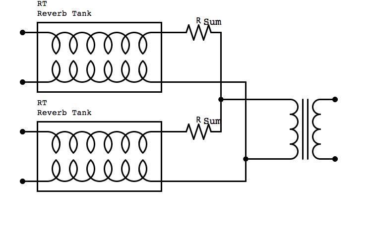
2. How does one connect the tanks on the output side? Through summing resistors into the output transformers? If I wire the outputs of a pair of reverb tanks in parallel, with summing resistors in series of each tank, like this:
reverboutput.jpg

does the output Z equal: (R Sum + Tank Output Z) in parallel with (R Sum + Tank Output Z) ?

I know some of this is real basic questions. Thanks for your help, Ben
 
OK I don't think I noticed this before - 800 ohms, so what if you change the accutronics part number to

type 9      E                            A                    (1,2,3)                      (A,B,C,D)                          1          A
        800ohm input        600ohm output    (s,m,l)decay time    connector options(x,x,x,x)  Lock    mount

I think I get it now, does having a fairly equal input and output impedence mean you don't have as much LOSS. if we never had to make up any gain wouldn't everything be passive...
They might have a 1:1 input transformer in there just to make sure that the system works with both balanced and unbalanced outputs... 


Latest posts

Back
Top