Hi there,
I wonder how will 990 DOA work in transformerless circuit? Need some help.
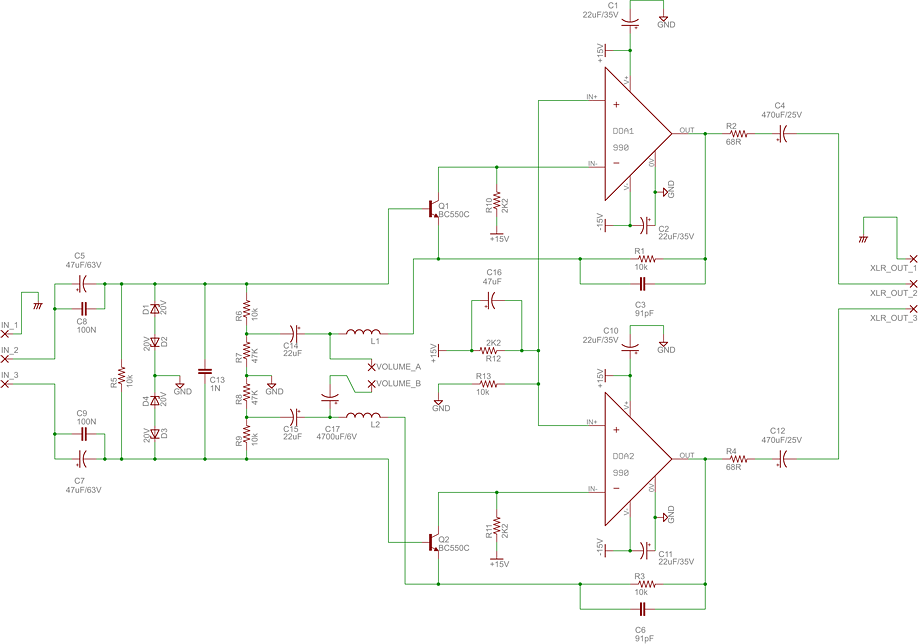
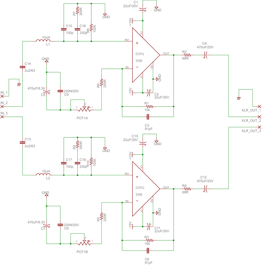
I took J Hardy's M-1 schematic [http://www.johnhardyco.com/pdf/M1_M2_M1p_20031025.pdf]and mixed it a bit with a 312 because I don't want servo in this preamp I'm building. Transformerless output section is from Jensen AS017 [http://www.jensen-transformers.com/as/as017.pdf]. Not shure how it will work :-\ Hardy's M-1 haves 150R:600R 1:2 transformer on input and 600:600 1:1 on output. Don't have any clue what to put in front of 990 DOA and how to tweak AS017 output to get best out of DOA?
this is progress so far
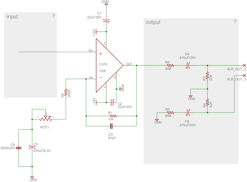
any ideas?
thanks
I wonder how will 990 DOA work in transformerless circuit? Need some help.
I took J Hardy's M-1 schematic [http://www.johnhardyco.com/pdf/M1_M2_M1p_20031025.pdf]and mixed it a bit with a 312 because I don't want servo in this preamp I'm building. Transformerless output section is from Jensen AS017 [http://www.jensen-transformers.com/as/as017.pdf]. Not shure how it will work :-\ Hardy's M-1 haves 150R:600R 1:2 transformer on input and 600:600 1:1 on output. Don't have any clue what to put in front of 990 DOA and how to tweak AS017 output to get best out of DOA?
this is progress so far
any ideas?
thanks

")