Racking Auditronics 110B modules

GroupDIY Audio Forum

Help Support GroupDIY Audio Forum:

This site may earn a commission from merchant affiliate links, including eBay, Amazon, and others.

Piotr

Well-known member
Joined
Jan 23, 2005
Messages
143
Location
Chambery, France
Hi !

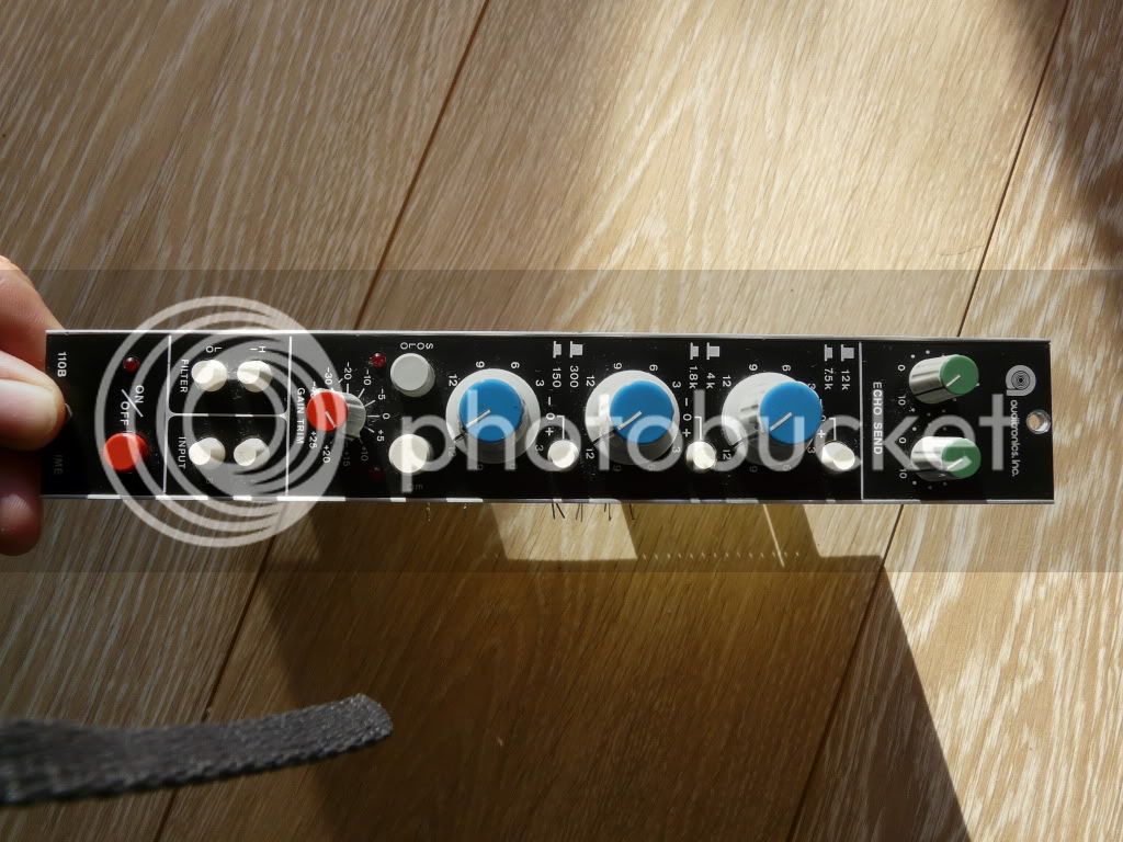
I've got 4 Auditronics 110B modules to rack.
P1040535.jpg

P1040536.jpg


I've already put two in a rack but they're not working properly. So I'm seeking for some advices and help !!! I'll describe the build and the problems as clearly as I can...

Here's the schematic link I've found in another thread on the topic: http://avensonaudio.com/tech/auditronics/audiotronics_110b.pdf or http://www.mediafire.com/?6ymbzyi2txv

As far as the power supply goes everything seems ok. I've used JLM Audio's AC/DC along with a 230V/2x15V toroid. http://www.jlmaudio.com/
The voltage rails are correct (+15V, -15V and 48V for phantom power). I've connected +15V to P2-1, -15V to P2-2, ground to P1-4). I've jumpered the +15V rail to the logic +24V rail (P1-15, while P1-14 goes to ground).

I've connected the input XLR via a JLM Go-Between (pad, phase and phantom switches) to the mic input, input A, on the module (P2-14 and 15, ground to P1-5).

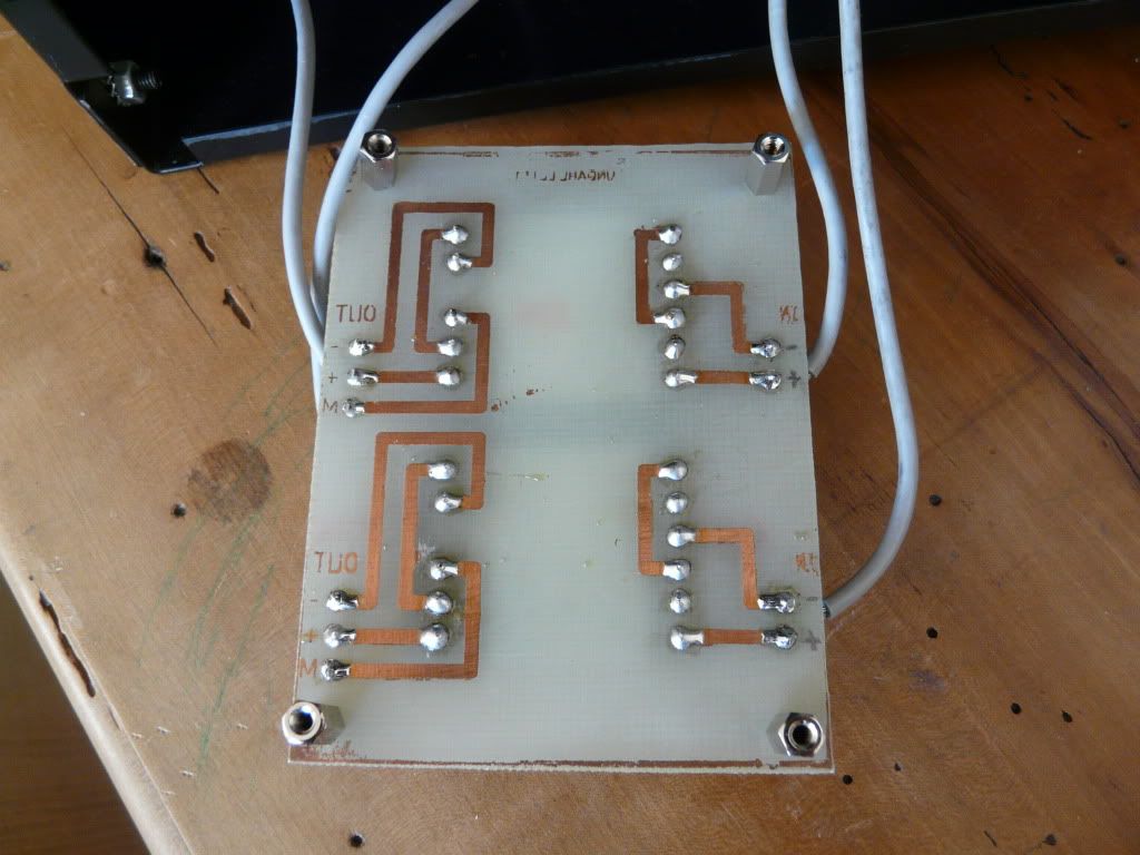
The output (P1-7 and P1-3) goes straight to a Lundahl LL1517 transformer (www.lundahl.se/pdfs/datash/1517.pdf) I've installed on a home made PCB as on their application white paper (+ to pin 1, - to pin 4, 3 connected to 6, and on the other side to the XLR, + to pin 7, - to pin 11, ground to pin 9, 8 connected to 12).

P1040533.jpg


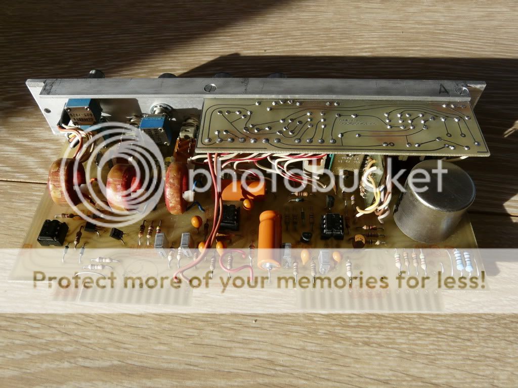
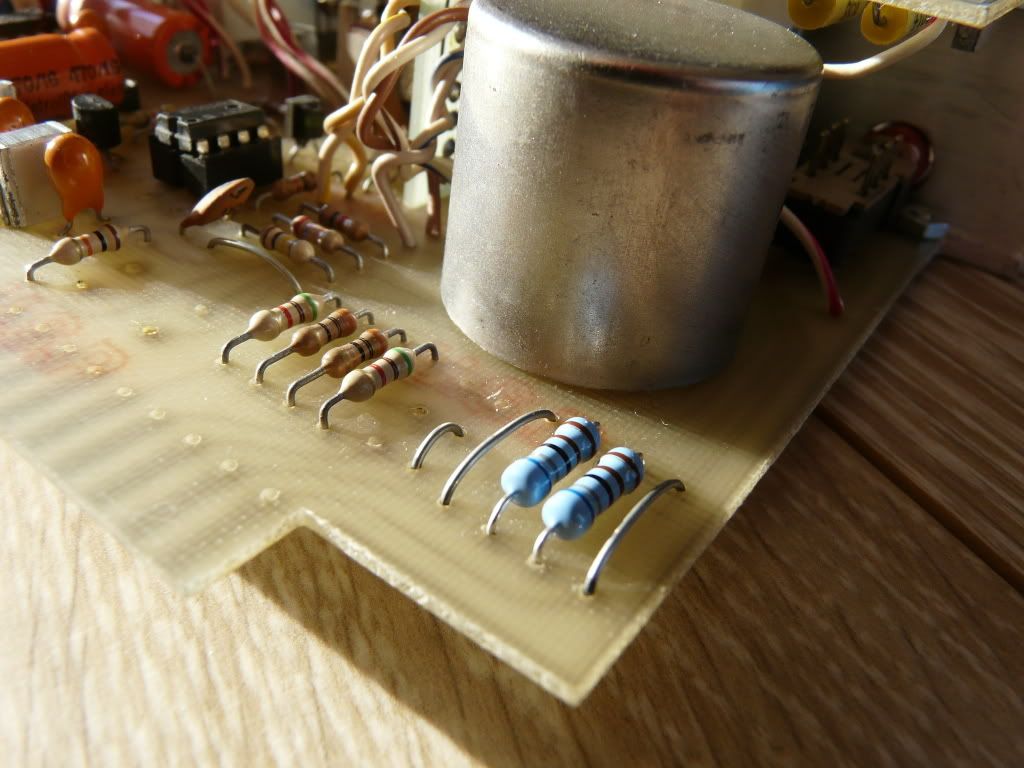
I've changed 6 dip tantalum capacitors (C8, C9, C0, C11, C14, C16) just to be on the safe side of things... They're the bright orange ones.

P1040538.jpg


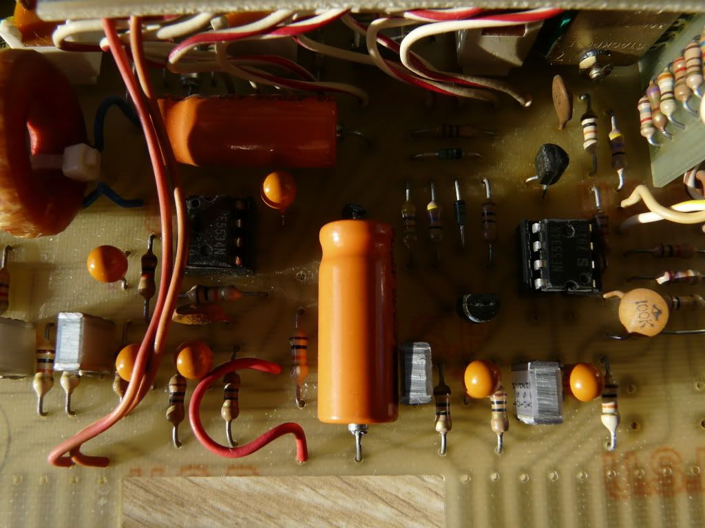
I've also changed two resistors (R1 and R2 from whatever they were to 6.8K) as Joe from JLM advised in another Auditronics thread. They're the blue ones on the right...

P1040537.jpg


Now, my first question is that of the output control. The modules have a "from fader" and "to fader" connections. If the connection is broken, no signal outputs. I've experimented with different values of resistors to simulate a connected fader (10K for example). This allows the module to output signal. But this signal is distorted and there also seems to be a grounding issue. I've got no idea of what's wrong...

Obviously I must have gone wrong somewhere, I'm pretty new to electronics so there are aspects of all this I surely don't understand...

I'll try to post pictures of the build later on and I'm open to all your remarks, suggestions and insight on this racking job !!!

Thanks a lot ! Piotr.
 
ok -  What normally goes between the to-fader and from-fader pins is a ......  fader. specifically, in these consoles, a 5k fader. A fader is the same electronically as a pot. The pot is not just hooked up as a simple variable resistor (wiper to one pin, one side of the pot to the other pin) but as a voltage divider http://en.wikipedia.org/wiki/Voltage_divider. One side of the pot is connected to the to-fader pin, the wiper is connected to the from-fader pin, and THE OTHER SIDE OF THE POT IS CONNECTED TO GROUND. So there are a couple ways to do this. The first and most versatile is to just a use 5k pot hooked up like a fader - this gives a level control after the preamp and before the eq - this way you can drive the input, and these channels sound absolutely awesome when driven for heavy psych drums and things. Second way is to put a fixed voltage divider using two resistors, to bring the level down about 10db - (It is recommended in the Auditronics 110 manual to keep the faders at -10 for best gain structuring/noise performance) see here for some pertinent discussion http://www.groupdiy.com/index.php?topic=29081.0. The third solution is to just jumper those two pins together - It will work fine - it's just like having the fader at max. Hope this helps, Best, Ben.
 
Thanks Plumsolly !

As far as what should be connected to the "fader" connection, thanks for clarifying the divider network and the value of it. That helps !!! I still need to understand what is wrong with the signal path and the resulting distortion...

Also does my output LL1517 stage looks ok ? And a typical grounding scheme would help, cause I feel something's missing...

All the best ! Piotr.
 
I'll be able to have a look at your output transformer hookup later as well as give a grounding scheme guide. In the mean time - you can always check if the output transformer hookup is the problem by unhooking it and running it unbalanced out. Best, Ben
 
Hi !

I'll try to run the output transformerless and let you know if it's sounding any better... Maybe I should also consider changing the NE5534Ns, we'll see !!!
 
I just had a look at your transformer hookup and it looks correct. I will have a look the grounding later if you are still having trouble.
Piotr said:
Maybe I should also consider changing the NE5534Ns, we'll see !!!
you should always explore these things on your own and see what you hear - having said that, I wouldn't expect any significant improvement (there are of course people who would disagree) As far as tangible results, IMO the time and money would be better spent on your next project.
Best and good luck - Ben
 
Great Ben !

Thanks for your trouble ! The Lundahl output doesn't indeed seem to be the source of the problem, but I'll check the unbalanced output route later on because... today's wednesday so the kids are out of school in France... Read no DIY for me today !!! I'll work on the preamps tomorrow and let you know what improvements (or none !) I've noticed... Thanks, Piotr.
 
Hi !

So today I've tried to unbalance the output of the modules and they sound better !!! It seems then an Auditronics 110B isn't able to drive a Lundahl LL1517... If someone is more knowledgable than me on the subject (not difficult since I'm a newbie !!!) I'd be happy to hear your opinion. So I've tested two modules and there seems to be other problems on the horizon !!!

To document this here are a couple of curves of the testing (using my Macbook Pro running Fuzzmeasure through a Sound Devices USB Pre). So the preamp section seems to be ok (even if bright considering the frequency response...) but if I engage the EQ section then things become very strange (I'll post pictures later on), might be a switch issue, more investigation to come... I'll keep you updated.

All remarks, ideas and insight welcome !!!

Cheers, Piotr !

Auditronics11OB-Curves.jpg
 
hmmm... lets try to rule some things out. Disconnect whatever you have hooked up to your to-fader pin and run directly from the to-fader pin to your sound card. This will bypass the entire fader>fader-buffer>eq>eq-makeup/output driver>output transformer section and isolate the preamp section. 
Piotr said:
It seems then an Auditronics 110B isn't able to drive a Lundahl LL1517...
I doubt that this is the case - I think those amp stages with the 5534 and the two transistors after it are pretty robust.
Best and good luck, Ben
 
Hi Ben !

Thanks for the test idea, here's the result... "To fader" (P1-11) output:

Auditronics110B-ToFaderOutput-0dBGa.jpg


And at different gains (without matching the soundcard's input gain), thought I'd check to be sure...

Audiotronics110B-ToFaderOutput-Diff.jpg


It's looking much more like a preamp, with a little limited hi end... Quite normal... So the problem then lies in another block. Before this test, I was jumpering "To fader" (P1-11) and "From fader" (P1-10) as you suggested. I'm planning on using one of the "Echo Send" pots which are 5Ks to control the "fader" output, more on that later.

Meanwhile I'll try to test all four modules, compare and post the results here. Hopefully some of them are OK.

Cheers, Piotr !
 
Hi ya all !

so I've progressed on the testing side of things !!! Here are the results, for each module with their serial number, at different gains (0db, -5dB, -10dB, -20dB).

This time the test setup is as follow: Fuzz Measure's sweep test signal>Sound Devices USB Pre>Auditronics 110B Input A ("to fader" and "from fader" jumpered)>unbalanced output (read no tranformer)>Sound Devices Line in>Fuzz Measure

One module seems to be defective preamp wise, check the hi frequency roll off. Another important info is that the EQ switches seem to be defective in different ways on all modules. Some cut the signal, some seem to be working in a "middle" position, I'll investigate what's happening with the switches later on, test them. Might be that there's some soldering the be refreshed, I'll try different things.

I'll keep you updated and documented !!!

Cheers, Piotr !

Auditronics110B-4modulescomparison.jpg
 
hi all.

i'm a new member here, and i signed up because i saw this thread..


believe it or not, i'm having exactly the same problem as you and i was wandering if you had solved it..


i'm using a JLM transformer and psu for +-15 +-24 +48 and 0v

i've wired up a 110a module and am getting the same, or a similar distorted output, with lots of buzz...


as far as i can see i've wired it the same way as yourself...
xlr goes into input a + and -,
shield goes to input common
outputs are program out and program common...


i'm currently testing without seperate output transformer,,,although i got the same result when i tested with it..


if you can offer any advice i'd appreciate it very much!!


ok, hi, and thanks for writing back.

there's been a change of circumstance...

i've bridged fader in to fader out,,,cos i have no pot at the moment,


with a bit of reading, and a bit more soldering, i'm pretty sure i have it all working the way it should,WITH the jensen output transformer...


my only problem now is,,,i don't have 48v connected,,,cos when i do connect it, i read 48v at all three xlr input terminals?


can anyone shed light on this?
 
Awesome! as per 48v: You have 48v on all pins referenced to what? Pin 3 should be tied to chassis ground which would make it impossible to have 48v on pin3 referenced to ground.
Best, Ben
 
ok, so erm,,,,maybe i forgot to ground that  :'(


good news and bad,,,

with it grounded,,,everything works as it should.

Phantom power works, all controls work. on off works,,,,,my new led meters work :)

the only problem is i'm getting a slight buzz/hum that i never had before...


i'm sure it's something i'l be able to sort all the same, but if there are any suggestions on the go, all the better...


ooh btw....,,,,what should be connected to ground, and what should be connected to 0V on the psu,,,,,or are they one in the same?

proper noob questions here,,,sorry about that!


hope you all had a great christmas! and thanks again for all the help.
 
Hey, good to hear. As far as grounding: connect 0v on power supply to power supply common (p1 pin4). Connect everything else that is a ground (Ac power earth on iec inlet, pin 1 of xlrs, program common, input common, and signal common) separately to a star ground point where you have removed some paint from the chassis and put a bolt through it - see Kubi's Jensamp pictures for reference http://www.groupdiy.com/index.php?topic=28546.0

Best, Ben
 
hmm,ok

there's something funny going on..

when i sorted my grounds from my 0Vs, the only output i get is a repeated electric kinda noise..


if 0V is connected to  ground it seems to work though......but presumably that's not the way to fix it.........


strange thing is too,,,,(with OV to ground) the output gain seems to be incredibly hot...like, from just talking, my protools input is peaking with the preamp gain at -10/-20, and there's a lot of hiss,but no buzz anymore! do you think is that just cos i've bridged the fader in/fader out terminals rather than using a pot?
 
Piotr said:
Hi !

I'll try to run the output transformerless and let you know if it's sounding any better... Maybe I should also consider changing the NE5534Ns, we'll see !!!

Actually DON'T if they are true Signetics brand, the logo is sorta squarish 'S'
DO change them if they are not!

I did not believe this until I tried it myself in a pramp design I built a couple of years ago that used them in a two stage design.
Somebody on the web pointed me to this and I found that the difference is more than subtle, I always tought a 5534 is a 5534, but they are not!

I don't want to start a debate here on which op-amp is the best, just my two cents on the fact that signetics 5534 are very good at what they do and the newer version lost some of the silkiness and a certain warmth the Sig's have.
Thanks, Luc
 
Back
Top