Gus' advice is good. What has become known as the Dorsey circuit is a very stripped down version of the Schoeps circuit. Having written similar articles, I understand that doing away with everything that's not essential was necessary in order to turn this circuit into a good beginners project. But if you're beyond the absolute beginner stage, you should have another look at the details left out.
Some random remarks:
The original version has a 60V dc/dc-converter for proper polarization voltage. Without it, the Dorsey version leaves only about 35V for capsule bias; you lose about 5 dB S/N compared to 60V.
The original version also has a bias adjustment pot which allows for lower THD and higher headroom. You only need an additional 1 Meg (precision) trimmer for that.
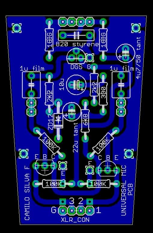
About your layout: commercial mic pcb usually use teflon stand-offs in the hi-Z area. Soldering the capsule wires and Gig-resistios to the pcb may invite leakage currents.
Also, 1u caps between the FET and BJTs may be a little large. There's practically no LF reduction going on other than those caps, and you may run into problems with sub-frequencies if you choose them this large. 470n is the largest value I would recommend. The original Schoeps circuit uses only 100n.


")