[BUILD] CAPI VP312DI~500/51x Series~Preamp + Direct Inject~Official Support Thread

GroupDIY Audio Forum

Help Support GroupDIY Audio Forum:

This site may earn a commission from merchant affiliate links, including eBay, Amazon, and others.
Eddie

As mentioned in the email, I would look at the nonworking Pad switch. Try reflowing the solder to that switch. That fact that it is not working is a big clue!
 
Hey,

i finished my 1st VP312DI but no sound at all. 48V works fine with a mic including the LED.
I started with with the quick Startup Testing Procedure and the problems are there ;)

Here my readings with no opamp and not connected to a power source:

-V and +V = 0
-V and C = 0
C and +V  = 4.7k
C and O = 6.2M
V+ and O = 6M
-V and O = 0

Everything should be way over 200k or?

OMG ;)

Thanks for any help, Sven
 
These look OK for a VP312DI.

Eliminate any possible, rack, cable, mic, converter etc problems first....then DOA's.
 
Everything external is fine here. I can switch to my JLM or OV560 with the same setup and they are running as expected.
What are the next steps? Measuring the +/-V and C sockets with connected power and they are +/-16V as expected.

Can i test with JLM99V op amp to see if the problem is there? I don't think so or, because they are working from 24-34V or?

btw. permanent VPR mode added.

Thanks, Sven

 
You can test with those opamps. Scroll thru this thread. Almost every conceivable issue has been discussed here previously.
 
OK the Zener Diode on PK2 was wrong positioned.
Now i hear the PK2 relay switching when i put a jack into the HiZ Jack. Still nothing comes out.
Should the Mic audiopath with a "good" PK2 working or can the whole audiopath with a wrong Zener in PK1 still be a problem?

Thanks, Sven
 
When should i hear the PK1 relay clicking?
Actually when i'am on 48V and put a jack into the HiZ, the 48V are away and if i'am remove the jack from the HiZ the 48V are coming back.

Again no audio at all.

Thanks, Sven
 
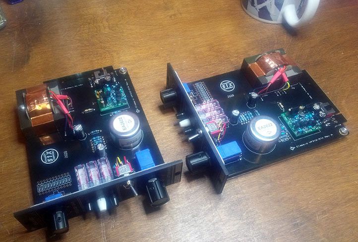
Here is a couple of vp312 just finished.

vp312_zps77539ef0.jpg


it just took me 6 hours to finish both units and GAR2520!!

ah...BTW they sound fantastic!!
 
My VP312 has been doing nicely for a couple of months now.  Then about a week ago the DI stopped working. The pre was at my band practice space so I haven't had a chance to look at it until today.  When I opened it up I noticed right off the bat that C12 has exploded.  It looks like it's in correctly polarity wise to me but perhaps I messed it up.  My first question is: Are the exploded cap and non-functional DI possibly related, or am I dealing with two separate problems?  The pre passes signal with the blown-up cap.
 
Did I miss anything hard wiring the SW2 connections?  What else could douse that cap to blow up other than a reversed polarity?
 

Attachments

  • IMG_3287.jpg
    IMG_3287.jpg
    435.2 KB · Views: 16
Also, in the meantime can I run the pre in "output cap bypass mode" to bypass C10?
 

Attachments

  • IMG_3288.jpg
    IMG_3288.jpg
    401.4 KB · Views: 20
As you can see in the pictures, I had the blocking cap in/out connector on incorrectly.  Running in cap bypass mode.  The DI works fine.  Still wonder what it was that made the cap blow up....
 
Typically, if that cap sees a voltage near or above it's rating it will blow. It almost looks like a bad leaky cap, not one that exploded but who knows. I would not run the pre in cap bypass mode without measuring the DC offset. Do you have a way of doing that? The pre will need to be on the bench flat in front of you while under power to check the DC offset.
 
Thanks for the reply.  I have one of your ribbon cable/extender card units so setting it out flat on the bench is no problem.  Where should I take the measurements?
 
Set your DMM to read DC voltage. Red probe to the top of R9 and the black probe to a good ground reference point like where the phantom LED is connected tot he top of the pushbutton switch.
 

Latest posts

Back
Top