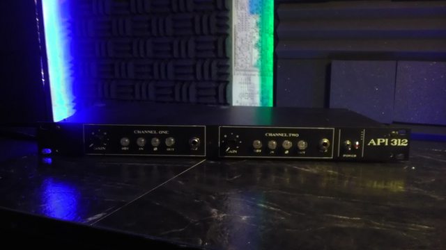
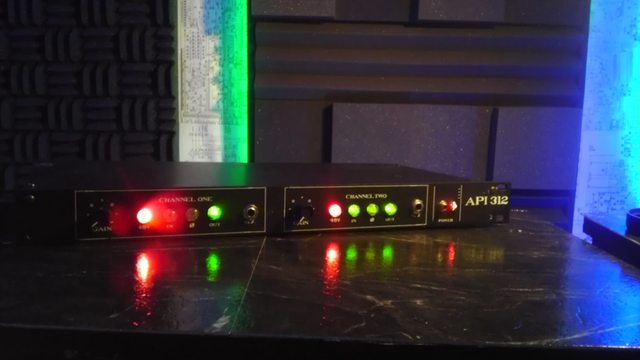
Mitsos API 312 / 990 Build Thread

GroupDIY Audio Forum

Help Support GroupDIY Audio Forum:

This site may earn a commission from merchant affiliate links, including eBay, Amazon, and others.
So I changed the Gar 2520 for a 1731 I had built around the same time and voila; I now have two beautiful punchy channels of API 312!!!  They sound great and I am positive will get a lot of use.  Thanks again for everyone who helped me.  And thanks again Mitso. 
Cheers`
 
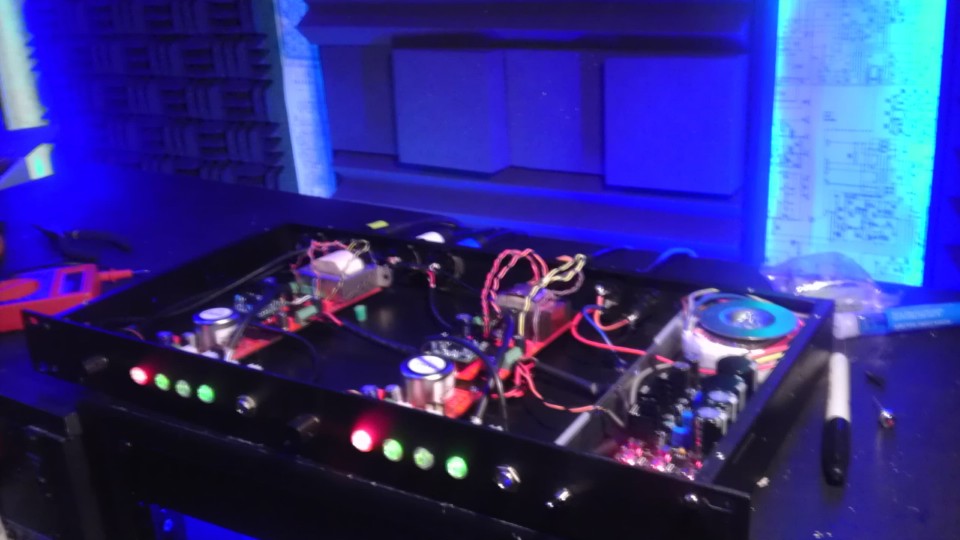
So I had planned on doing my own silk screening using the gear we had used for my bands patches and tshirts but the dude who has all the stuff (ink, screens, metal-fab know how) to get it all done is just dragging his heals and I grew frustrated and decided to go another route. So the final front panel will still be a bit but i wanted to post some pics anyways.  Being a greenie and missing some brain matter from my adventurous and often path-less-chosen past I am actually pretty proud at how great these sound.  Definitely comparable (if not superior) to my other API and API-ish clone pres. 

uHi6LrQ.jpg


Unfortunately they only had green/blue in 4pdt pushbutton switches at mouser and digikey so my options had gotten limited.  Thanks Nielsk for the red ones.  Still the switches glow and that's bad ass.
I plan on implementing a vu meter but haven't decided if I am going to go led or analog.  I built some led ones but I don't love them.  Maybe jlm or app????

h0kbpR6.jpg


XVYUOsa.jpg


LQvc5Al.jpg


They both have ed andersons input xfrmrs but I used a cinemag output with a sl2520 "red dot" on one and a gar 1731 and an ea2503 on the other.  I plan on probably going with red dot and cinemag on both as i just got some ml-12's from WRA I want to stick the ea outputs on.
These sound great BTW.  I have already tracked a few acoustic guitars and some drums with them.  I am incredibly happy.  ;D
 
Nice build! I'm sure they sound great..

FWIW, you can change the LEDs in the switches, they are just normal 3mm LEDs with their legs bent at 90 degrees and stuck  out the bottom of the switch.  OF course, you have to be very careful because the switch contacts can fly out and if you lose them the switch is useless...
 
That's an awesome tip. I'll definitely be careful; I had two brake while in my possession and received a broken one from digikey so I know how delicate they can be.
 
Final pics.  I decided to just do homemade front panel until extra cash allows me to purchase one from FPD.  I just couldn't have it sitting on the bench any longer and needed to rack it.

w9fW8Tml.jpg


KccK59Sl.jpg
 
i am probably the last one still with the pcbs from the group buy !

finally started building 4 channels of M1 preamps

I was wondering what was you experience with the gain control

10K rev log pot is good enough ?
 
finally started building 4 channels of M1 preamps
I was wondering what was you experience with the gain control
10K rev log pot is good enough ?

Stepped switch is recommended & what I used (12 position grayhill w/ pcb from CAPI). See the John Hardy Doc if you haven't already.
 
Yes, def a switch is the easiest way to go. With a pot you lose a lot of resolution at high gains. Do take a look at John Hardy's docs, notice he uses a custom dual pot for the M1, with a "high/low gain" switch to switch between the two gangs of the pot. You can use a grayhill with a pcb or if you're on a tighter budget an alpha or lorlin will do the same job. 
If you want smaller gain steps use a 24 position, Elma is best, but the chinese 'uraltone' type will work on a budget.
Good luck!
 
I was aware the switch is better.

But not cheap !

These are ok ?


http://www.mouser.it/ProductDetail/Grayhill/56DP30-01-1-AJN/?qs=sGAEpiMZZMvNbjZ2WlReYhndqMY8foDII9cjW32P%252bKk%3d
 
you might want to look for a shorting switch, the non shorting may cause pops when switching.  I'd get the grayhill from classic api with the little PCB (about $15-20) or an Alpha from Mouser.  ($3). 
 
ahh. that´s actually a nice upgrade for my beloved API312. Do you just order the kit as is and its just a replacement for the pot?

cheers
M
 
Hi sorry, I just saw this. I haven't used Jeff's kit, but yes, it would replace the pot. To ensure your gain range stays the same, you should check with him what R and C values he uses in the feedback path and shunt part. If those are the same as on your PCB then his kit should replace your pot seemlessly.  You can also use your own resistors and customize the gain steps and range.

cheers!
 
i am almost finished my four channel unit.

i have done an homemade pcb for the grayhill switch.

how do i calculate the resistor values for the gain switch ?

the hardy schematic shows the resistors for a 16 position gain switch and i'm using 12 position instead

 
The easiest way to do it would be to figure out what gain steps you want, keeping in mind that you have 6dB of gain from a 1:2 input transformer.  Are you using a 1:1 output?

Opamp gain in this case is Rf/Rs + 1 .  That's the feedback resistance divided by shunt resistance + 1. 

In the JH M2, he uses 10K feedback and 5K total switch resistance.  10/5 + 1 = 3x voltage gain which is 9.5 dB.  Add the 6dB from the trafo and you get to the 15dB minimum gain on his front panel.  See how it works?

You can use this site to convert dB to voltage gain and vice versa:

http://www.muzique.com/schem/gain.htm
 
should i do 4dB steps ?

from 15 to 59 dB

yes i'm using 1:2 in and 1:1 out.

would like to try out the transformerless output as well, in that case i need another resistor configuration on the gain switch ?

thank you
 
I spaced mine evenly,
60-15=45
45/12 = 3.75.

4 decibels will get you to 63 top gain which is pretty good.

Later, after actually using it you'll know if you want smaller steps in a specific region, and then you just recalculate from there to the end.
 
Hi
This is what I'm trying to do.

Does this look like I got the values correct?

Also I have some 25k Rev log switched pots that I've made but they are the type that break contact when turning, will this create a big thump? Anyway round this other than buying some normal 22k Rev log pots?

48v wise i was thinking of going with how the access 312 schematic does it.

The line balancer doesn't seem to have the 51R and the 10k resistors?

Be good to get a word on these changes and if there is a better way.

Regards

Spence.
 

Attachments

  • image.jpg
    image.jpg
    1.1 MB · Views: 37
I don't see any glaring issues.  All the R values are what I normally use, and are known working.  You can change any and all of them to fit your needs.  Did you check the BOM?  It has descriptions of most components function and some suggestions for "critical" parts.

As for the gain switch, I can't tell you.  I remember a forum member burdij (he has a store called grove audio or something like that, more into DIY synths nowadays) told me once that he always used non-shorting switches and never had an issue.  I have always used shorting without any issues.  Since you have them done already, just stick them in there and see if there are any issues. 

For the zobel and load R check with Sowter.  10K load R seems low.  What is the step-up ratio of the trafo, and what opamp are you using?  You are going without caps in the signal path,  you may want to consider using the servo, and maybe even the bias circuit, to null the offset, if that proves to be a problem.

I have no idea how the access 312 does phantom, but if you follow it exactly I'm sure it will be fine, lots of those PCBs around over the years.

The line balancer is meant for a THAT 1646, the 51R and 10K I believe are used with DRV134 chips. The THAT doesn't use them, check the datasheet, use panasonic bipolars (or other high quality bipolars in those spots).
 
wow, where'd you get that cut info?  Got any more?  It's got a BBC BBC number on it...  Anyway, it looks like a line input to me, you can try it if that's what you're going for (API even had a 1:1 trafo called the 2621 I believe)  but for a mic pre using a 2520 you need a much higher ratio, 1:7 or higher.  A 990 is better suited to lower ratios, again, this is not the ideal trafo for mic pre usage, but you can try it if you've got it lying around.  PPA used to have a few opamps suited for low ratio input transformers. 

If you've already got the trafos and 2520s the give it a shot, otherwise rethink things a bit and you'll end up happier in the end. 

good luck
 
Back
Top