SA-3A (LA-3A Clone) Support Thread

GroupDIY Audio Forum

Help Support GroupDIY Audio Forum:

This site may earn a commission from merchant affiliate links, including eBay, Amazon, and others.
Can't find any info here but I just sent an email to the member who sold it to me.
As a matter of fact he posted in this thread not long ago; Siegfried Meier.
Just to confuse things a bit more I have a vague memory of it being Par Metal, hmmm....

I'll be back!
Cheers//M
 
Incredibly similar. Same metal "texture", same upper cover with grid on the back, same structure...
Very curious...
 
I'm sorry I don't have any more detailed information. Maybe try searching this thread (press the print button ikon and use ctrl F). I know Siegfried is in Canada, Par-Metal is american and Modushop italian...
I guess you crosschecked photos of both...

Good luck!!
Best
//Magnus
 
By the way, I have to wire the board  to the front panel pots, commutators, Vu-meters and 230V transformator.
Do you know if there is a pdf file edited for that by serpent audio, or if I have to refer to the schematics ?

 
If I remember correctly it's pretty well explained on the schematic with some drawings
(It's been a while on my shelf, got tired of Molex crimping ;) )
I made a handmade drawing for myself, I'll dig it up and snap a photo...

//M
 
Found my drawing, don't laugh... :D
The switches and gainpots are seen as mounted on the frontplate while looking at it from inside the case,
if that makes any sense (from the back).
The green colour indicates shield. Green colour by the switches and meters that says nc means not connected.
And the rest, black goes to black and red....

Since I haven't wired mine yet I can't guarantee the drawing is correct.

Cheers //M


Attachments

  • image.jpg
    image.jpg
    1.4 MB · Views: 107
Thanks ! So we had to double check ... !!!
Sad that Serpent Audio did not edit a pdf with all drawings and advices in one document.
He doesn't seem very active. Most of the times, you get no answer if writing to him by email...I wrote him several times and never got answered at the exception of two cases : for payment..., and another time very shortly (one sentence).
Anyway...His SA-3A board seems very nice. Hope I won't have too much problems of hum after cabling.
Will keep you all in touch if any interesting remarks.


May gave been good if Serpent could have checked and validated the drawing from Dr Gris !
Serpent ?
 
Hey all!

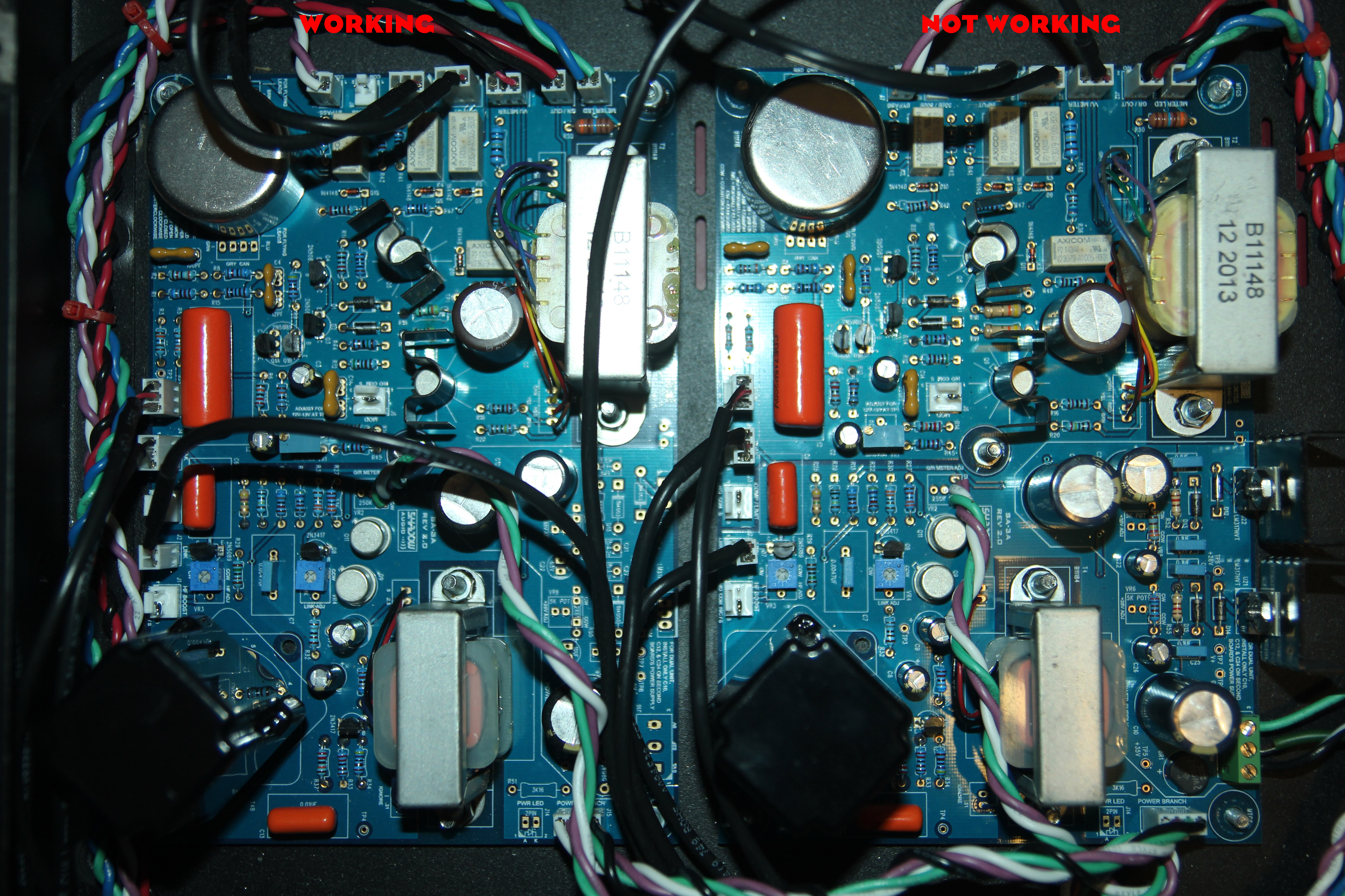
I just completed my pair, one works perfect buuuuuuuuuuuuuuuuut not the other. It passes audio, but hi-passed to death and not with so much gain. The needle hardly moves when the gain is maxed out. Voltages at test points read ok, I already changed every transistor but the matched pair, but voltages here match with the other channel. Where should I look?
Oh... and the working channel sounds delicious, of course!!

Thanks for your help guys!!
 
Just a quick question: What kind of power switch can y'all recommend for this build? No power switch was included in my kit, yet I see most of the finished-build-shots from other builders show the same kind of shielded barrel type switch. I can't find any mention in the BOM either. Thanks!
 
sharpeleven said:
Just a quick question: What kind of power switch can y'all recommend for this build? No power switch was included in my kit, yet I see most of the finished-build-shots from other builders show the same kind of shielded barrel type switch. I can't find any mention in the BOM either. Thanks!

You can use exactly the same switch as any other switch on the build. The barrel shield you see on many builds is just DIY. This unit is very AC sensitive, so anything you can do to limit humming is worth doing it. ;)
remsouille said:
Hey all!

I just completed my pair, one works perfect buuuuuuuuuuuuuuuuut not the other. It passes audio, but hi-passed to death and not with so much gain. The needle hardly moves when the gain is maxed out. Voltages at test points read ok, I already changed every transistor but the matched pair, but voltages here match with the other channel. Where should I look?
Oh... and the working channel sounds delicious, of course!!

Thanks for your help guys!!
Any help on this? Anyone? :'(
 
You checked all the wiring and capacitors for sure, but comparing every component to your working channel didn't solve the mystery?

Maybe a hd picture of your PCB would help us to trace the error...

cheers
 
nickhepfer said:
You checked all the wiring and capacitors for sure, but comparing every component to your working channel didn't solve the mystery?

Maybe a hd picture of your PCB would help us to trace the error...

cheers

Hi Nick,

I did check components and wiring about a thousand times, now. At least visually.
Here is what I know:
-Not a psu problem, as the working channel is powered by the non-working one.
-I replaced every transistor on the board.
-reading at test points are fine.
-signal gets in and out in bypass, so not a in/out wiring issue.

I'm running out of ideas on this one  :'(

Here is the hi-res picture if it can be of any help
Thank you!!
JQ0aL1c.jpg

 
I am trying to accomplish the stereo adjustment. I can get them both to set the meters to zero with the gain. When I turn on the GR switch I can get channel A to register gain reduction on meter A. I also can get channel B gain reduction to adjust meter A but not its own meter. Any thoughts?

Thanks in advance

Bonsaimaster
 
remsouille said:
Hi Nick,

I did check components and wiring about a thousand times, now. At least visually.
Here is what I know:
-Not a psu problem, as the working channel is powered by the non-working one.
-I replaced every transistor on the board.
-reading at test points are fine.
-signal gets in and out in bypass, so not a in/out wiring issue.

I'm running out of ideas on this one  :'(

Here is the hi-res picture if it can be of any help
Thank you!!
Ok, I found something. My input trafo was dead. I replaced it, and I could see gain reduction happening, but no output... And while trying to figure out what was going on, I somehow shorted Q4 and fried R11 and R17.
SO I replaced Q4, R11 and R17, but with power on, R17 still fries instantly.... Maybe R11 would as well, I haven't kept the unit powered long enough to see that...
I'm seriously considering throwing the board away and building a new one, unless on of you guys has an idea...
 
Hi everyone.
My rig is up and running but there seem to be a problem with the GR section.
I turn both channel CW at stereo adj. signal generator at -8 in PT . if I turn the peak pot to 5 on both channel... the primary reads around-5GR but the secondary reads almost -14GR.

I swapped peak knobs and T4B but stil the same readings.

VDC and VAC read the same on both besides the TP2 . around 1.2VAC at primary and around 0.850vac at secondary. in mod/50db and comp mode.

odd thing too, when I set the primary to limit, the TP2 drops around 0,960VAC and the GR gains around 1dbGR (-7 to -8 for example). The secondary board do not change at all GR and VAC wise.

I tried to turn the secondary stereo adj to match the primary GR but it feels wrong that there is almost 10GR difference when in equal state.

Am I the only one to have experienced that ?  Anyone can help me troubleshoot this??

I tried to measure resistors but some readings are off since they are soldered at the board. but both channel reads the same resistance wise.

                  Channel 1  /            Channel 2
TP1 12.00VDC   12.00VDC
TP2   1.129VAC           0.812VAC
TP3        20.37VDC                20.23VDC
TP4        33.95VAC   34.46VAC
TP5 34.99VDC   34.99VDC
TP6 28.55VDC   28.55VDC
TP7 43.30VDC   43.30VDC
TP8     0.00VDC               0.00VDC

thanks a lot and dont stop DIYing like hell!!

-Fred-
 

Latest posts

Back
Top