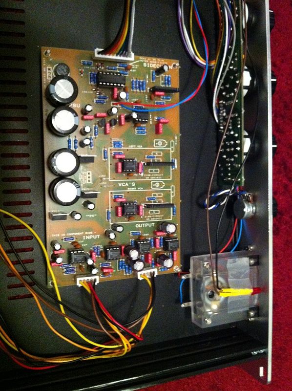
GSSL HELP THREAD!!!

GroupDIY Audio Forum

Help Support GroupDIY Audio Forum:

This site may earn a commission from merchant affiliate links, including eBay, Amazon, and others.
main repairman said:
,bass loop,, and output unit i not hear change. I do not understand the sense HPF without change the sound output unit.

The high pass cuts the low end from the signal that the compressor reacts to..  The example you posted has a very static low end (and not a very pronounced one to boot), so changing the high pass will not be that dynamic of an effect - more like adjusting the threshold.

Theres a nice  explanation here.

http://www.sknoteaudio.com/wp/index.php/2015/12/16/sidechain-high-pass-filter-compressor/

Try a standard drum loop with a kick and snare. Engaging the high pass will make the compressor reach relatively less to the low end.

Gustav
 
Thanks.  And you know you recommend any test a unit that I saw the result of a change HPF on an oscilloscope?
I send to the unit sine and square signal and to output unit i saw only change amplitude. Its correct?
 
main repairman said:
Thanks.  And you know you recommend any test a unit that I saw the result of a change HPF on an oscilloscope?
I send to the unit sine and square signal and to output unit i saw only change amplitude. Its correct?

Depending on the frequency you set on the filter, see if switching the filter in and out affects the amount of compression with a test tone under that frequency..

If you really want a high pass in the signal path, which seems to be the main issue, just add the filter to the signal path!?


Gustav
 
Gustav thank you one more time for a help and patience!! Now I understand path of if it much better. 
Last thing that bothers me.

On the main board all is working just as it should but I'm having problem with Turbo board which I think is same replica of Sidechain Path.

Problem is with a ratio switch. I play some sound to compressor. Left channel is main board sidechain and the right is Turbo mod sidechain.

RATIO 2 = Left channel shows me 4 Gain reduction / Right channel shows me 4 gain reduction.
RATIO 10 = Left channel shows 4 Gain Reduction / Right channel (Turbo Mod) shows me 20 db gain reduction.

I haven't changed any settings.

I'm sure that problem is in Turbo Mod, but tell me please how does Ratio affects Threshold?

THANK YOU !!!!!
 
Olegarich said:
Gustav thank you one more time for a help and patience!! Now I understand path of if it much better. 
Last thing that bothers me.

On the main board all is working just as it should but I'm having problem with Turbo board which I think is same replica of Sidechain Path.

Problem is with a ratio switch. I play some sound to compressor. Left channel is main board sidechain and the right is Turbo mod sidechain.

RATIO 2 = Left channel shows me 4 Gain reduction / Right channel shows me 4 gain reduction.
RATIO 10 = Left channel shows 4 Gain Reduction / Right channel (Turbo Mod) shows me 20 db gain reduction.

I haven't changed any settings.

I'm sure that problem is in Turbo Mod, but tell me please how does Ratio affects Threshold?

THANK YOU !!!!!

I dont undestand "Right channel (Turbo mod)". Could you be more specific about what you are measuring (side chain or signal path), and where you are seeing differences?

As for how the ratio affects the threshold, I am not smart enough to grasp the whole picture of the ratio circuit, all I can tell you is, that the ratio does affect the threshold. Someone smarter may be able to help if youre looking for a break-down of it. It shouldn't be necessary to get the unit working, though.

Gustav
 
What I ment to say is.
When you insert Turbo Mod, you have 2 side-chain lines.
In Gyraf version 2 - 47K resistor going in to the sidechain section. If you adding Turbo mode, you lift one end of 47 K resistor which goes to second side-chain circuit which is Turbo Mod. So I called Left channel is sidechain which is hapening on the main board and right channel is sidechain that hapening on the Turbo Mod.

 
Olegarich said:
What I ment to say is.
When you insert Turbo Mod, you have 2 side-chain lines.
In Gyraf version 2 - 47K resistor going in to the sidechain section. If you adding Turbo mode, you lift one end of 47 K resistor which goes to second side-chain circuit which is Turbo Mod. So I called Left channel is sidechain which is hapening on the main board and right channel is sidechain that hapening on the Turbo Mod.

I understand the side chain VCA split, but the control voltage to the signal path VCAs are still summed, so what I am trying to understand is (sorry if I am just being really slow - hot day here :) ), if one side is compressing more - signal path - , or you are referring to something in the side chain, if you are feeding the unit a stereo signal, if you are going one channel at a time, etc.

Just to keep things simply, lets ignore that for now.  Did the compressor work as expected before adding the modification? If it did, you can narrow the error down the the implementation of the modification. If you never tried without the modification, remove it, get the basic circuit working, then add the mod.

Gustav
 
Yeah it worked well without Turbo, so I'm tracing there. Yet, a newbie question just to be sure. I'm using 8027-B 1mA meter. There are lighting there but I don't know what voltages are needed, how you measure that kind of stuff? Sorry for that  newbie question.
 
Hi all!

Im doing some mods and upgrades to my working gssl and im replacing the lorlin switches with grayhills as they started to feel loose and weird.

Does the ratio switch have to be 3 pos 4 pole? Im only able to find 6 pos 2 pol with the specs i need (4mm shaft etc) and i looked at the layout and cant figure why i could not use a 6 pos to pole switch limited to 3 positions?

-Markus
 
I'm not Pro like Gustav and others but control board (RATIO) uses one pole and then i see traces goin in to 3 possitions, if you planing to use Turbo mod, then you need another pole and 3 possition for that. 
So, i think it's gonna work well.  (2 pole , 6 positions)
Not sure if you insert that pole to the control pcb traces  if it will match  right, but if you wire it with cables then should be no problem there.
 
Olegarich said:
I'm not Pro like Gustav and others but control board (RATIO) uses one pole and then i see traces goin in to 3 possitions, if you planing to use Turbo mod, then you need another pole and 3 possition for that. 
So, i think it's gonna work well.  (2 pole , 6 positions)
Not sure if you insert that pole to the control pcb traces  if it will match  right, but if you wire it with cables then should be no problem there.

Yah im planning to wire the switches
 
I have a Rev. 11 or 12 PCB Grinder GSSL board that seems to be working (the metering is responding) but the compression seems to be subtle (if non-existent); the LED doesn't seem to turn on all the time either. The problem is that the circuit board isn't connect to chassis (the 3 holes that are grounded with the stand-offs have paper washers over them).

It seems like the circuit is working (i.e. the metering is responding to the front controls) WITH the chassis ground connected BUT there seems to be a ground loop somewhere as the sound is distorted and at a lower volume. When I disconnect the circuit board's 0V cable that comes from the BAL IN section: I get audible sound but there seems to be hum and the compression isn't as drastic (especially the bypass) when the chassis ground is disconnected.

I've been searching through the forums but have to look through close to 400 posts so would rather just hope if some one out there might know where a ground loop on the PCB Grinder board might exist- as I'm certain I need to connect the main board to chassis ground. Furthermore- it seems like consolidating (and deciphering  the different revisions of the GSSL) seems prudent: given that I have the latest (at the time of this writing) version (so all the prior issues were likely resolved while some other ones have likely cropped up).

I've resoldered most (if not all) the points (albeit I'll probably be doing it again) but I first want to find out if there are any possible trouble areas that might need fixing (especially if there are any traces that might need to be broken). 

I've read trying out the CRCRC filter (albeit a schematic would be helpful), along with placing the bridge rectifier off the circuit board (keep in mind that those are non-PCB Grinder versions).

The biggest point of contention I'm having is why I can't connect the main circuit board to chassis ground (and why the compressor seems to work "better" with it connected- albeit with distorted/low sound when connected to chassis ground).

If there are any test points with voltage ranges to check: that'd also be great.
 
bxt403 said:
If there are any test points with voltage ranges to check: that'd also be great.

I think this would probably be the best place to start.

First off, disconnect the transformer, check to make sure you are getting 30V from side to side, 15V from center tap to each side (AC).

Hook up the transformer to the board, check for in- & output (DC) voltages on the 7815 and 7915 regulators in the PSU with reference to the ground/center tap on the transformer. (google 7815 pinout and 7915 pinout to see which pin is what).

Google "5534 pinout" and "5532" pinout to check for the pinout, check the positive and negative voltage pins throughout the build with reference to ground (should be 15V on the + and - pins)

Check your XLR connectors to see if you made a mistake hooking it up.

The LED sometimes not firing up could be a symptom of a latching 7815 regulator, or a more basic build error.

The symptoms you describe are not indicative of a ground loop or design issue, so I would advice you to pursue basic trouble shooting measures, rather than look for board design errors.

Edit:a picture of the build often helps, since the most obvious errors sometimes stand out. Its most  likely you have an error in your transformer and/or XLR hookups.

Gustav
 
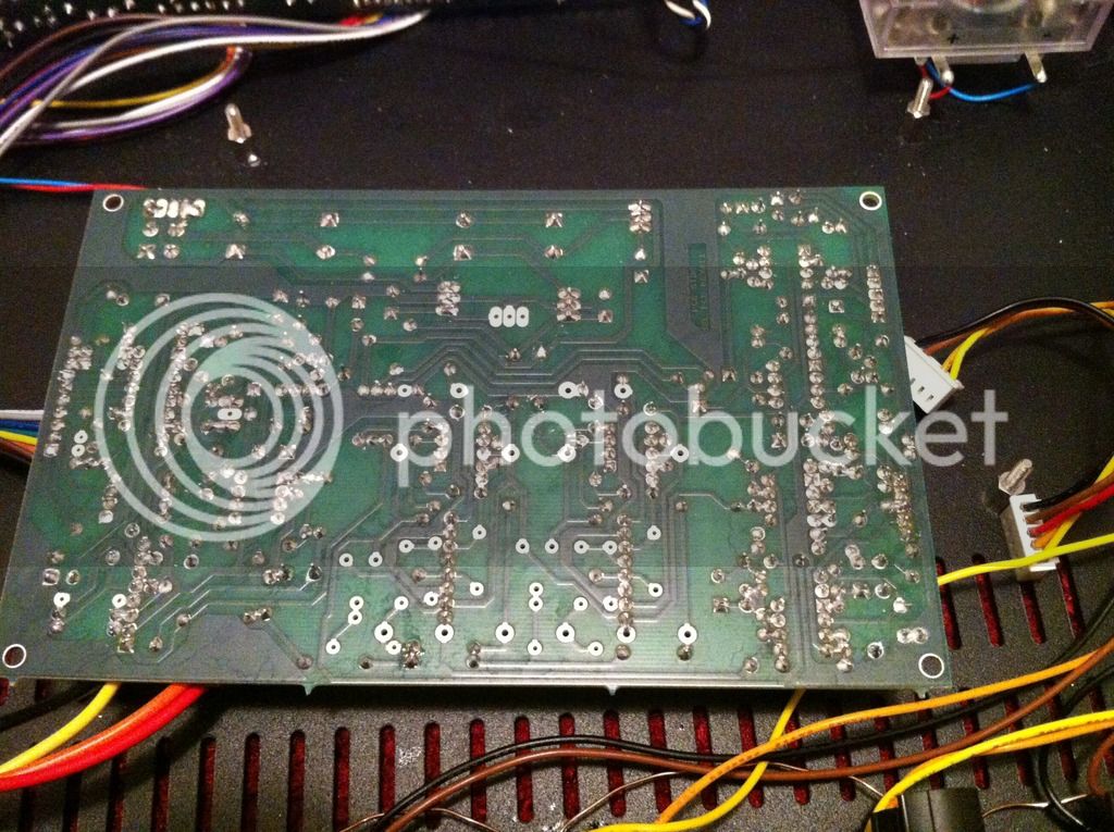
I decided to rebuild the main circuit board (given 2 Rev. 11 PCBs were supplied and since a new fault would crop up after faulting something else).  The original build was faulted to the point where both sides of stereo signal were audible but the meter (and compression) weren't active.  I transferred the resistors and ceramic capacitors but replaced almost everything else (excluding the Signetics ICs).  The That VCAs are 2180Bs but I replaced them (given the size of the parts order, I figured I might as well be sure I have some spares in case any need replacing). 

I've metered the 15 volt regulators (and they're slightly off but assume that 's normal @ ~ +14.83V & -15.12V): the input ICs are reading a few mV (around +/-  0.3 to 3 mV) at the outputs but both of the VCA 5534's are reading around -100mV at the outputs).  I'm get -1V at the CTRL input of the 2180B + NE5534 VCA DBX equivalent circuit and traced the control voltage of the TL072.

Regardless of signal present: audio passes through but the compression and meter have no effect. Every control has not effect- with the exception of the GAIN knob (and the bypass switch disables/reduces the volume increase when enabled).  The SC switch has no effect. I neglected to measure the CV with or without the Bypass switch enabled- only when it was off.

The GAIN Reduction meter worked before (and the needle still jumps when I power on the unit). The VCA circuits for both the left and right channels have the same control voltage (and the audio is present and clearly audible albeit compression has no effect). 

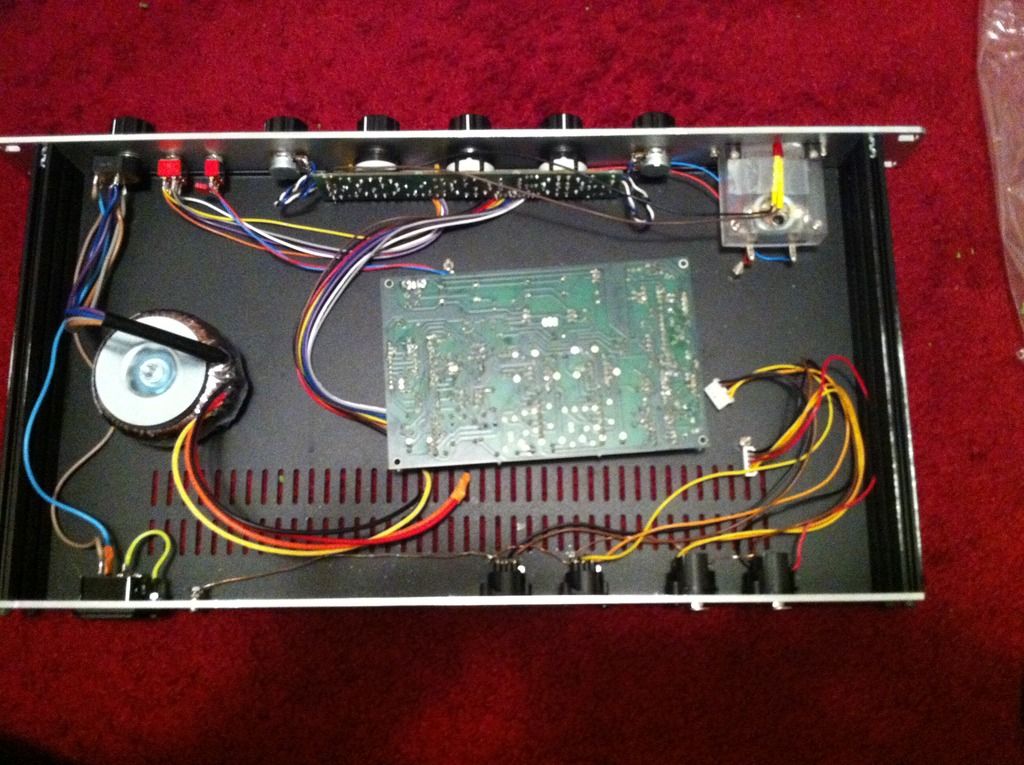
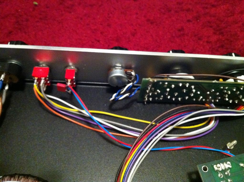
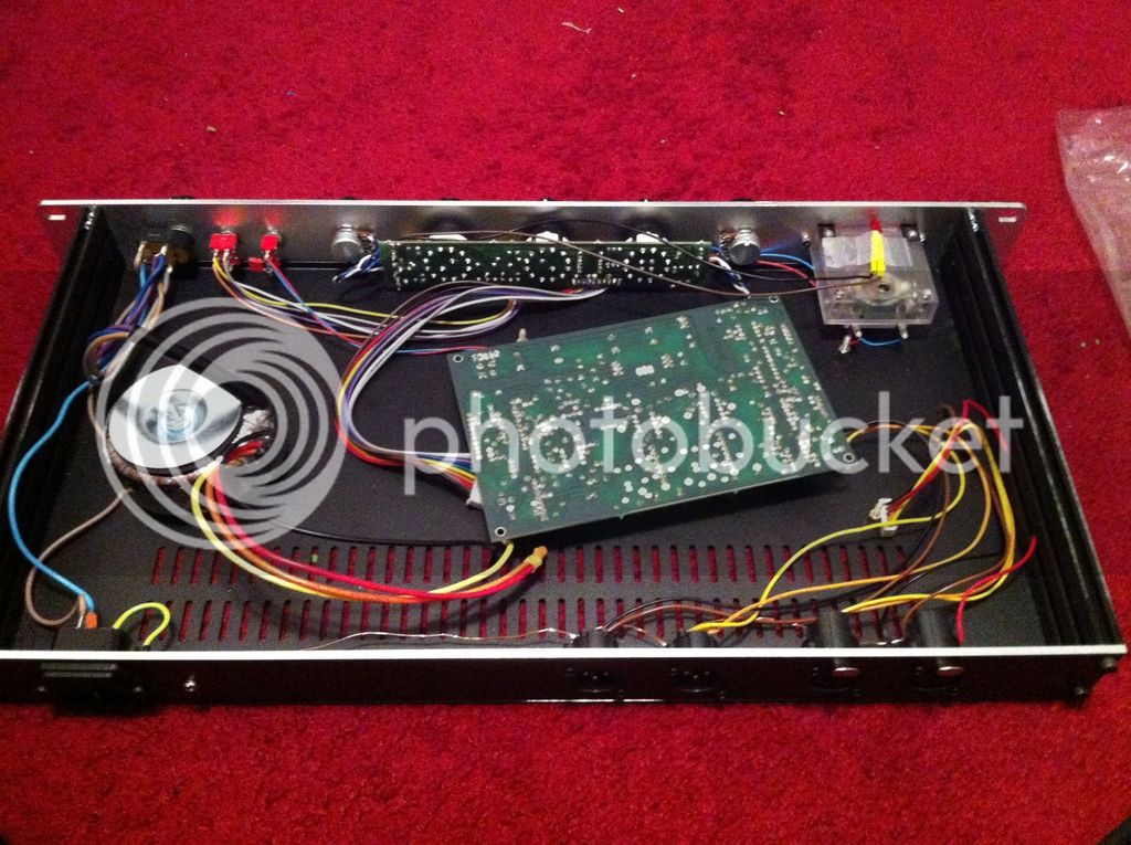
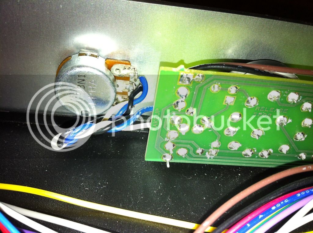
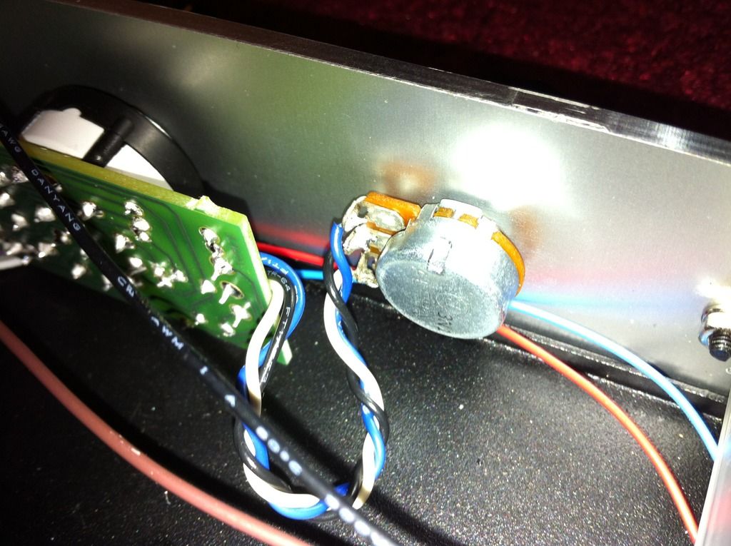
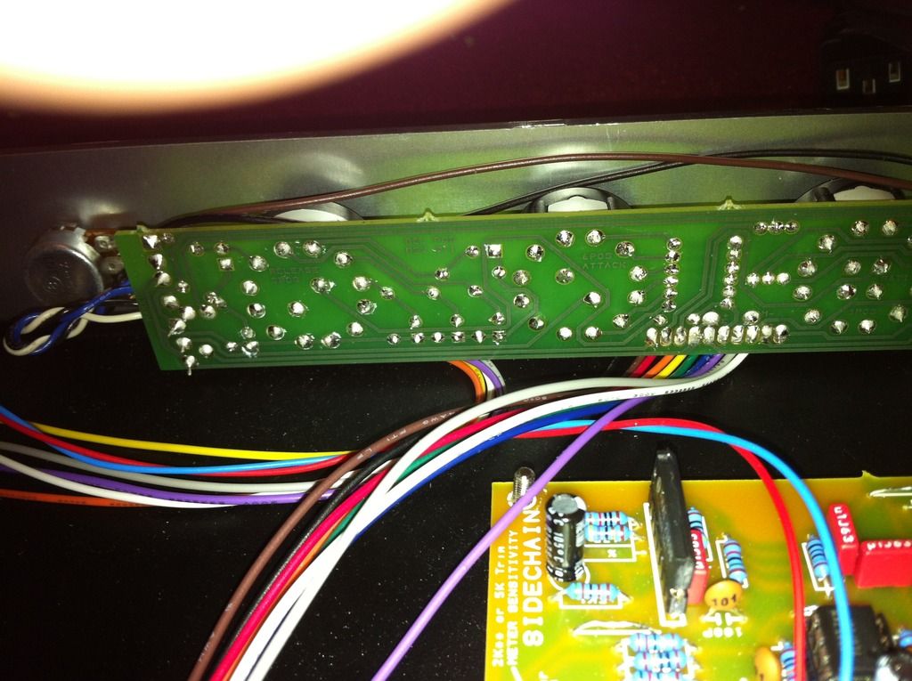
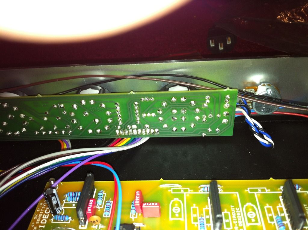
The photo in the instructions shows the pots on either side of the front control pcb being wired straight across (i.e. the vertical sequence is the same for the coloured wires connecting from the PCB and the pots).  I'm using twisted wires but the colour of the wire matches between the pot and PCB pads.  Note: I disconnected the power trafo to take the photos (I'm certain the voltages are within tolerance- given a stereo signal's passing though albeit without any effect).  The LED is also illuminated when the unit's powered on.

I'm thinking there's a short or something that I can't see- depending on what voltages I should expect from the CV circuit (in particular around the TL072). 

Any help is appreciated: especially since the PCB Grinder website has the Rev. 12 documentation.


bxt403 said:
Any help is appreciated: especially since the PCB Grinder website has the Rev. 12 documentation.

There are no revision changes that would account for the gravity of your problems. They would be minor in comparison (noise optimisation, adjusting the range of a pot, filtering the PSU etc).

First thing that jumps at me on your build is, that you seem to have isolated the center tap on your transformers secondaries with heat shrink. This is incorrect - you need to connect the secondary in series (as you have done), then connect the center tap to the center of the power input on the PCB , and each side to each side.

If you do it correctly, you will have 30VAC from side to side, 15VAC from either side to center, check on the PCB before the bridge if you have doubts about he connection.

Gustav
 
Gustav said:
bxt403 said:
Any help is appreciated: especially since the PCB Grinder website has the Rev. 12 documentation.

There are no revision changes that would account for the gravity of your problems. They would be minor in comparison (noise optimisation, adjusting the range of a pot, filtering the PSU etc).

First thing that jumps at me on your build is, that you seem to have isolated the center tap on your transformers secondaries with heat shrink. This is incorrect - you need to connect the secondary in series (as you have done), then connect the center tap to the center of the power input on the PCB , and each side to each side.

If you do it correctly, you will have 30VAC from side to side, 15VAC from either side to center, check on the PCB before the bridge if you have doubts about he connection.

Gustav


It's not pictured but the centre tap wires are shorted to a single cable that was/is connected inside the heat shrink.  That is- the centre tap was/is soldered to the middle ground pad for the AC input. I don't see how shorting the centre tap wires to a single cable that's soldered to the middle pad is going to make a difference (aside from making sure everything's neat and I have enough usable cable from the power trafo which is why I did it that way).  I was getting around 16 or 17 VAC from either side but I had three cables connected- the black on one side, shorted to a single cable( orange & red) to the middle pad, and yellow at the other outer pad.
 
bxt403 said:
I don't see how shorting the centre tap wires to a single cable that's soldered to the middle pad is going to make a difference

Me neither - I just wanted to make sure you didn't end it in the heat shrink (thats what it looked like on the picture to me).

I also failed to realise you had done another board, and you are now passing audio, but just not getting compression.

Meter kick is normal on start-up, and if it kicks up, you have it connected correctly.


1. I would double check the SC high pass point (fastest way to do it is to solder a jumper from side to side on it to exclude the switch as the culprit).

2. I would double check the wiring of the bypass switch.

Since youre passing audio, I dont suspect you have any problems with your supply voltages, but just to make sure, measure the supply voltages on the ICs (not in and output pins, but voltage supply pins).

Gustav
 
short question:

Is 1/8W good enough for the pots? The Alpha's with 1/2W are currently not availible at mousers.
Then i would use this one, i hope it has a nice feeling though.
http://www.mouser.de/ProductDetail/Alpha-Taiwan/RV16AF-10-15R1-B50K-LA/?qs=sGAEpiMZZMtC25l1F4XBU1WvpdUcjC%2f6vI3LuCnK6evMwmL049rD%252bg%3d%3d
 
Back
Top