GSSL HELP THREAD!!!

GroupDIY Audio Forum

Help Support GroupDIY Audio Forum:

This site may earn a commission from merchant affiliate links, including eBay, Amazon, and others.
Gustav said:
bxt403 said:
Firstly- I think we're on a different page (given I was under the impression we BOTH were understanding the problem : you seemed to address the issue nicely and read that I desoldered the wires). [/URL]

I am not sure what went wrong, but as  long as the center tap is connected, like the latest picture shows, thats good.

bxt403 said:
I'm certain I'm getting the right voltages for the power supply

Great, would you mind posting the values, just so we can verify?

bxt403 said:
At the end of the day- the only things I need to know is where on the circuitboard (that I've more or less ruled out)  should I look for abnormalities w.r.t. the SC toggle not having any effect; along with the majority of the front panel controls.  Keep in mind I'm passing audio (and the GAIN knob's working when the BP switch is off)  so I only want to know the general area of where to look w.r.t. no compression occurring. 

Passing audio is good, but its impossible to guess what the exact issue is. Its best to exclude the most basic variables first, so - you already mentioned you found one error on your bypass switch wiring, so there could be another, but before doing that...


bxt403 said:
this build's power supply voltages are all measuring in the proper ranges

It would be extremely beneficial to trouble shooting if you would post the values.


bxt403 said:
The other thing I'm thinking is perhaps switching out older component values from prior revisions- as the posted schematic includes the design changes (as it might be related to using a 2180B vs 2181B). 

I found this page to be useful ( http://diy.fischerworks.com/gssl_vca.shtml )- as the person referenced the THAT data sheets for the 2180 and 2181.

Note: the PCB-Grinder kit I have came with the 2180B and "Matt's DIY Pages" seems to indicate that the THAT datasheets have the circuit board set-up (with the 5K1 resistor  and "%" elsewhere in the Left/Right VCA  sections) for the 2180- although Pages 2 & 3 of the GSSL schematic list that  Rev. 9 incorporates the THAT 2181 under the "Revision History" heading.  Also there's a discrepancy between the 120K* resistor (that's pink on "Matt's DIY Pages" and is valued at 100K).  The footnote at the bottom of Page 1 of the schematic states "FOR THAT2180 VCA's DISCONNECT PIN4" but noticed that those pins are open and the components aren't populated on the Rev. 11 circuit board I have so am certain the 2180Bs that came with the "Full Kit" I bought don't need to be modified.

I am sorry if I was not clear earlier.

Looking for alternative IC brands, turbo boards, PSU filter boards, looking  for traces to cut and values to change is a waste of time. Your unit is not compressing, so you have a basic build error or component failure.

Edit: If you are unsure of how to check the voltages, let us know ,so we can properly help. Its not a problem if you dont know, but its a problem if its the reason you are not giving feedback on voltages.

Gustav


It turned out to be the adapter cable I was using (mini-plug from my Macbook Pro 1/8" audio out to stereo XLR): I had one for input to the GSSL and one for output to my Objective 2 headphone amplifier). 

The output cable was working fine (and was wired correctly with a 150 Ohm resistor connected between pins 2 & 3). The input cable going into the GSSL was wired in reverse (in that it was wired for an XLR-M but had pins 1 & 3 connected on an XLR-F connector to an XLR-M to M barrel adapter).  I didn't notice the barrel connector compensates for the pin reversal until I replaced the XLR-F with a proper XLR-M.

Prior to testing with a properly wired test cable, I changed the Signetics NE5534As and NE5532As that were installed instead of the stock T.I. NE553xPs- with Signetics NE553xNs; along with changing the TL072 from a new one to an older one I have. 

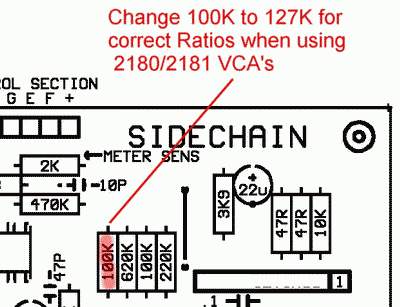
Also- I noticed that a Rev. 7 or Rev. 8  board seems to need 127 K Ohm resistor installed where it's labelled as 120K* on Rev. 9 or later (as it's listed on Gyraf GSSL page):
ratio_2180.jpg


Knowing 120K is for the THAT 2181, according to the table (at http://diy.fischerworks.com/gssl_vca.shtml).  My  research (thus far) indicates (verifying from the PCB photos at audiokitchen) is that the 100K Ohm value (and DBX 2150) is at least up to the Rev. 7 PCB and 127K Ohm is for the THAT 2181 & 2180  (from the picture from the GSSL page on Gyraf's website but is contradictory to the Gyraf Rev. 9 schematic & "Matt's DIY Pages"). 

The table at "Matt's DIY Page" indicates the proper value is 120 KOhm (and the 127 K Ohm value listed on the Gyraf page implies that 120 K Ohm value listed for the  2181 on the Rev.9 (along with the Rev. 11 & Rev. 12) schematic also applies to the 2180 (but it isn't mentioned on the schematic).  It's safest to assume that  the 127K Ohm value might need to be double checked; given I'd rather not waste any more time trying to figure out if the 127K Ohms is correct or not on Rev. 8 or earlier versions of the GSSL: where the DBX 2150 is labelled at the 3 VCA slots that are labelled as THAT 2181 on the Rev. 11 boards I have (that's consistent with the Rev. 11/12 schematic that's posted at PCB Grinder at the time of this post). 

Furthermore- it seems like you're better off finding an older Rev. circuit board  (Rev. 8 or earlier) if you want to implement the DBX 2150; conversely- use a Rev.9 (or later) board if you want to implement the THAT 2181 or 2180 (knowing that the silkscreening on the Rev. 11 boards I was provided were labelled consistently to accommodate the THAT 2180- despite having "THAT 2181" silkscreened).

Also- it looks like Rev. 11 incorporates the CRC & HP filter so it's a safe assumption that adding an external CRC filter (like the one from EXPAT Audio)  is redundant (and a waste of space, time and money for any people who are using the Rev. 11 or later circuit board).  The compression seems to be more noticabe with the 553xP/N that the 553xAP/AN installed at the input and output but I've only used Signetics (N & AN) ICs (since they're true to the SSL design) so am not sure of how the newer Texas Instruments P & AP versions of the 553x op amps sound (w.r.t. to the original SSL circuit).

Finally: I'm thinking the SSL X-Logic Bus Compressor (or any current SSL Bus Compressor variation) is going to sound closer to Duende Native (in that you're going to hear the authentic SSL sound- albeit Duende's Bus Compressor is based around the 4000 G Series) while I'm inferring the GSSL is an optimized and/or improved version of the 4000 E.  I can only compare my build to SSL's Duende Native's Bus Compressor (and my GSSL  doesn't sound as "SSL-y" but suspect it's because Duende is meant to sound more like an optimized version of the 4000 G).
 
tglsnell said:
Gustav said:
tglsnell said:
Hi Everyone!

I've been reading this thread since I started building my GSSL and its been a lot of use.

HELP! I powered my GSSL up today...nothing. None of my LEDs light up and no audio passes through the unit.
The needle on the VU meter also hits hard left and stays there until power off.


On testing with a voltage meter:

1. The LED feed only measures 0.46 volts
2. I get 29.8 volts across the two bridges located between the two VCA's
3. The voltage feed to the VU meter was 9 volts

I'm not really sure where to go from here in terms of the best way to find the fault or if anyone can suggest anything? I have given this thread a read and not seen anything on my specific issue. Any help or advice would be greatly appreciated. Thanks in advance guys.

Picture: https://www.dropbox.com/s/gd33apw2ub14v89/IMG_1468.jpg?dl=0

Additional details:
PCB/Components from PCB Grinder
Push Button Switches and VU meter from Don Audio
UK based so 230volts if that helps at all

Start by checking he 12V regulators output.

Gustav

The three regulators read:
7812 - 12 volts
7815 - 15 volts
7915 - 7 volts

Thats devinitely not right.  7812 output pin should be +12V, 7815 output pin should be +15V, and 7915 output pin should be -15V.

Recheck that you are measuring the correct pins for the 7915, and check if you reversed polarity (just using the probes the "wrong" way around" on the other regulators.

If the others are fine, but you are indeed getting -7 on the 7915, check whats on the input pin.

Gustav
 
Gustav said:
tglsnell said:
Gustav said:
tglsnell said:
Hi Everyone!

I've been reading this thread since I started building my GSSL and its been a lot of use.

HELP! I powered my GSSL up today...nothing. None of my LEDs light up and no audio passes through the unit.
The needle on the VU meter also hits hard left and stays there until power off.


On testing with a voltage meter:

1. The LED feed only measures 0.46 volts
2. I get 29.8 volts across the two bridges located between the two VCA's
3. The voltage feed to the VU meter was 9 volts

I'm not really sure where to go from here in terms of the best way to find the fault or if anyone can suggest anything? I have given this thread a read and not seen anything on my specific issue. Any help or advice would be greatly appreciated. Thanks in advance guys.

Picture: https://www.dropbox.com/s/gd33apw2ub14v89/IMG_1468.jpg?dl=0

Additional details:
PCB/Components from PCB Grinder
Push Button Switches and VU meter from Don Audio
UK based so 230volts if that helps at all

Start by checking he 12V regulators output.

Gustav

The three regulators read:
7812 - 12 volts
7815 - 15 volts
7915 - 7 volts

Thats devinitely not right.  7812 output pin should be +12V, 7815 output pin should be +15V, and 7915 output pin should be -15V.

Recheck that you are measuring the correct pins for the 7915, and check if you reversed polarity (just using the probes the "wrong" way around" on the other regulators.

If the others are fine, but you are indeed getting -7 on the 7915, check whats on the input pin.

Gustav

Hi Gustav,

Just rechecked that voltage against the schematics and I've got the correct readings. It must of been something to do with how I measured it.

I have however discovered two new occupancies.
My feeds to and from the LED, both measure 10 volts. Neither are grounded. Discounting one wire and connecting the LED directly to ground causes it to function properly.

2ndly the centre pin on the 9812 actually measures 22volts and the voltage across both terminals on the meter is a continuous 10 volts on both terminals independent from each other.

I can't seem to figure out if that voltage should even be there.
 
tglsnell said:
Gustav said:
tglsnell said:
Gustav said:
tglsnell said:
Hi Everyone!

I've been reading this thread since I started building my GSSL and its been a lot of use.

HELP! I powered my GSSL up today...nothing. None of my LEDs light up and no audio passes through the unit.
The needle on the VU meter also hits hard left and stays there until power off.


On testing with a voltage meter:

1. The LED feed only measures 0.46 volts
2. I get 29.8 volts across the two bridges located between the two VCA's
3. The voltage feed to the VU meter was 9 volts

I'm not really sure where to go from here in terms of the best way to find the fault or if anyone can suggest anything? I have given this thread a read and not seen anything on my specific issue. Any help or advice would be greatly appreciated. Thanks in advance guys.

Picture: https://www.dropbox.com/s/gd33apw2ub14v89/IMG_1468.jpg?dl=0

Additional details:
PCB/Components from PCB Grinder
Push Button Switches and VU meter from Don Audio
UK based so 230volts if that helps at all

Start by checking he 12V regulators output.

Gustav

The three regulators read:
7812 - 12 volts
7815 - 15 volts
7915 - 7 volts

Thats devinitely not right.  7812 output pin should be +12V, 7815 output pin should be +15V, and 7915 output pin should be -15V.

Recheck that you are measuring the correct pins for the 7915, and check if you reversed polarity (just using the probes the "wrong" way around" on the other regulators.

If the others are fine, but you are indeed getting -7 on the 7915, check whats on the input pin.

Gustav

Hi Gustav,

Just rechecked that voltage against the schematics and I've got the correct readings. It must of been something to do with how I measured it.

I have however discovered two new occupancies.
My feeds to and from the LED, both measure 10 volts. Neither are grounded. Discounting one wire and connecting the LED directly to ground causes it to function properly.

2ndly the centre pin on the 9812 actually measures 22volts and the voltage across both terminals on the meter is a continuous 10 volts on both terminals independent from each other.

I can't seem to figure out if that voltage should even be there.

Centre pin on the 7812 should measure 0.

You seem to have basic supply problems. Start from the beginning, the trafo unconnected, work from there.

Gustav.
 
Hey Gang,

I just bought a GSSL off of Reverb.  I've been comparing it to another GSSL (which I purchased this one to replace due to its makeshift enclosure, lack of a proper VU meter, and general ugliness), as well as the Waves SSL plugin and I'm finding some significant differences with this unit.

When compressing drums, for instance, I generally use a 2:1 ratio with a slower attack and quicker release, and can get either very little compression, or gobs of it depending on how I've set the threshold. However, with this unit, I'm having a hard time getting much compression (to my ear) using those settings, even with the threshold at minimum.  Feeding it a drum mix with the threshold at minimum, the VU meter is reading 6-8 dB of gain reduction, but flipping back and forth between "In" and "Bypass", there is very little difference sonically, which is not at all the case with my other unit or the plugin.  Also, with both my other compressor and plugin, 20+ dB of gain reduction is no problem using those settings.

I also tried feeding a sine wave through it at those settings (perhaps not the most practical approach), and found only an 8-10dB difference in output between the minimum and maximum positions on the threshold knob. 

Any ideas on what might be causing this?  Is that the way it is supposed to behave?  I've attached a pic of the unit, if that helps at all.  It took a hit during shipping, and the left rack ear was bent pretty badly.  I was able to bend it back to the point where I can at least rack it.  No loose connections or other visible damage from shipping, as far as I can tell. 

Thanks!

C
 

Attachments

  • FullSizeRender.jpg
    FullSizeRender.jpg
    1.3 MB · Views: 64
Colorblind said:
Hey Gang,

I just bought a GSSL off of Reverb.  I've been comparing it to another GSSL (which I purchased this one to replace due to its makeshift enclosure, lack of a proper VU meter, and general ugliness), as well as the Waves SSL plugin and I'm finding some significant differences with this unit.

When compressing drums, for instance, I generally use a 2:1 ratio with a slower attack and quicker release, and can get either very little compression, or gobs of it depending on how I've set the threshold. However, with this unit, I'm having a hard time getting much compression (to my ear) using those settings, even with the threshold at minimum.  Feeding it a drum mix with the threshold at minimum, the VU meter is reading 6-8 dB of gain reduction, but flipping back and forth between "In" and "Bypass", there is very little difference sonically, which is not at all the case with my other unit or the plugin.  Also, with both my other compressor and plugin, 20+ dB of gain reduction is no problem using those settings.

I also tried feeding a sine wave through it at those settings (perhaps not the most practical approach), and found only an 8-10dB difference in output between the minimum and maximum positions on the threshold knob. 

Any ideas on what might be causing this?  Is that the way it is supposed to behave?  I've attached a pic of the unit, if that helps at all.  It took a hit during shipping, and the left rack ear was bent pretty badly.  I was able to bend it back to the point where I can at least rack it.  No loose connections or other visible damage from shipping, as far as I can tell. 

Thanks!

C

Hard to tell by looking at the picture - may be some problems due to the gold can implementation, but couldn't say.

Gustav
 
Hi there guys,

Quick update, managed to get my GSSL passing sound. No compression just yet but I think thats due to blown out IC's as one of my voltage regulators was outputting 14volts instead of 12 which I believe might of caused an IC to go.

Long story short I have to order new IC's and the minimum order for free shipping is £30. So I'm ordering all the components for the Turbo and superside chain mod.

Now because I'm combining the turbo mod and the SSC, I need to SSC boards. I'm assuming I need a 12 position, 2 pole Lorlin switch...but these don't seem to exist. I can only find 1 pole versions. Am I mistaken or can anyone suggest an alternative?

Tom
 
tglsnell said:
Hi there guys,

Quick update, managed to get my GSSL passing sound. No compression just yet but I think thats due to blown out IC's as one of my voltage regulators was outputting 14volts instead of 12 which I believe might of caused an IC to go.

14V would not kill any of the ICs used here.  I would be concerned that you have a short somewhere, or a misplaced regulator, or...start from the basics, check supply voltages.

tglsnell said:
I need a 12 position, 2 pole Lorlin switch...but these don't seem to exist. I can only find 1 pole versions. Am I mistaken or can anyone suggest an alternative?

They dont exists (not as far as I know, at least). you'll have to find an alternative, or use a 2 x 6 and live with being limited to fewer frequency points.

Gustav
 
Gustav said:
tglsnell said:
Hi there guys,

Quick update, managed to get my GSSL passing sound. No compression just yet but I think thats due to blown out IC's as one of my voltage regulators was outputting 14volts instead of 12 which I believe might of caused an IC to go.

14V would not kill any of the ICs used here.  I would be concerned that you have a short somewhere, or a misplaced regulator, or...start from the basics, check supply voltages.

tglsnell said:
I need a 12 position, 2 pole Lorlin switch...but these don't seem to exist. I can only find 1 pole versions. Am I mistaken or can anyone suggest an alternative?

They dont exists (not as far as I know, at least). you'll have to find an alternative, or use a 2 x 6 and live with being limited to fewer frequency points.

Gustav

I've not found a suitable alternative yet, do you know of any?

Supply voltages all seem fine right up until the 78L12 which is 14 volts instead of 12. I can't seem to find a short anywhere and there seems to be a decent amount of resistance between ground and most of my components. I'm really hoping its a failed IC as I get audio passing through the unit when the compressor is both on and in bypass mod but the Attack switch for some reasons seems to attenuate the signal slightly. Make up gain and threshold pots do nothing.
 
I need a 12 position, 2 pole Lorlin switch...but these don't seem to exist. I can only find 1 pole versions. Am I mistaken or can anyone suggest an alternative?

Alternatives (2x12) can be found on Ebay -- not Lorlin though.
 
Script said:
I need a 12 position, 2 pole Lorlin switch...but these don't seem to exist. I can only find 1 pole versions. Am I mistaken or can anyone suggest an alternative?

Alternatives (2x12) can be found on Ebay -- not Lorlin though.
... and if you would count the steps needed for all on board selectable options, you might realize that you only need 8 positions per switch pole or per deck ...
... there are some open frame rotary switches around for cheap ...
 
Thanks guys, I did find the switches off eBay in the end.

I'm having some serious issues with the standard unit at the moment though. I've spent the last couple weeks trouble shooting it and I've replaced every single IC.
I get audio passing through it, both when the unit is active and when it is bypassed. I also have fully functioning make up gain but i don't have any compression what so ever. This is true on both channels.

All my voltages going into each board are correct and I've replaced a couple of dud voltage regulators which were part of my original problem.

Two things I've noticed, I'm getting a fair amount of hiss from the unit and that when switching the attack switch on the unit, the meter position increases towards the 5db mark.

Any suggestions on what might be the problem or any top trouble shooting tips would be incredibly helpful. I'm hoping its not completely ruined.
 
Hello again guy, just finished a GSSL but of course i run through a problem i dont find a solution  :-[ ( classic )

My unit is pretty quiet

When i run the bypass switch, the volume goes pretty normal, when IN BYPASS i play with the attack or release, it mutes the signak in some positions...

I tried with different THAT 2080, no different, changed the TLO74, no differences, checked of course the soldering, tried another front pannel ( fron another units ) no difference

i dont have NE 5532or34 spare to try to replace ( for now )

any suggestion ?
 
ok i found a track i guess my resistor reseller is an A****e

i found 2  20Kohn resistors ( close to the TLO75 ) where in fact 20Ohms so i will check all my resistors one by one

also trhe 120K was 97k...

I replaced them, now the volume is good, but the Attack and thresholds dont works ( release works ) ...
 
So after a whole day of crazyness i replaced al the resistors with correct values to be sure

now i got a problem ( again again again )

in bypass,  sound is normal but attack and release make the sound get loud and distorded

when i switch to normal no compression  no action from the commands except make up gain

i compared with the other units i got and i got a major difference by mesuring the resistor 3.3M, i mesure 1.5M ( the + on one side of the resistor and the - on the other side ) and 3.5 M( going down ) when i reverse the + and - of the multimeter

seems like a capacitor or diode issue but now i am lost

any advice ?
 
i changed all the diodes, same problem ( no compression ) the 3.3M seems normal ( so a diode was off ) and soind got distorded

Also i noticed that if i remove the jumper of the side chain, i still ahve sound ( on the others i dont have sound at all )

the front panel and the vu meter PCBs work properly ( tried to exchange with the others i have and work )
 
last update :)

so after overcleaning, checking the board 100000000 times, changing all the ICs all resistors, comparing with the other units i manage to make it work almost normaly
all is good except the input volume that is pretty low

in by pass or not the sounds is great but less loud than the other units

compression is normaland still works withouth the HPF jumper

all values are similar on all units ...

i dont get it

there us 20dB of difference ( more or less between the units )
 
Hi,

I got a little problem with the led of the vumeter, that I've noticed that the light is really weak, so I checked the voltage I had on the led and I measured only 2,07 volts, I measured the same values on the pads where are soldered the led wires. Is it normal. Other than that my unit just works fine.
 
innercityman said:
Hi,

I got a little problem with the led of the vumeter, that I've noticed that the light is really weak, so I checked the voltage I had on the led and I measured only 2,07 volts, I measured the same values on the pads where are soldered the led wires. Is it normal. Other than that my unit just works fine.

Perfectly normal, if you want a brighter LED, lower the value of the drop resistor a bit.

Gustav
 

Latest posts

Back
Top