Planning my BA-6A

GroupDIY Audio Forum

Help Support GroupDIY Audio Forum:

This site may earn a commission from merchant affiliate links, including eBay, Amazon, and others.

letterbeacon

Well-known member
Joined
Jul 12, 2009
Messages
642
Location
London, UK
I've yet to completely finish my BA-2 pre amp, but seeing as I'm in my home town for Christmas and physically far away from the unit, I thought I'd turn my attention to theory behind my next project - the RCA BA-6A.  I have the vintage input and output transformers for this unit (thanks to emrr) so I'm very keen to pursue this!

I've managed to glean a lot of knowledge and information from DaveP's brilliant thread, but I'm doing a couple of things differently to Dave (a tube power supply for one thing) and I would appreciate some advice from my learned friends on the board.

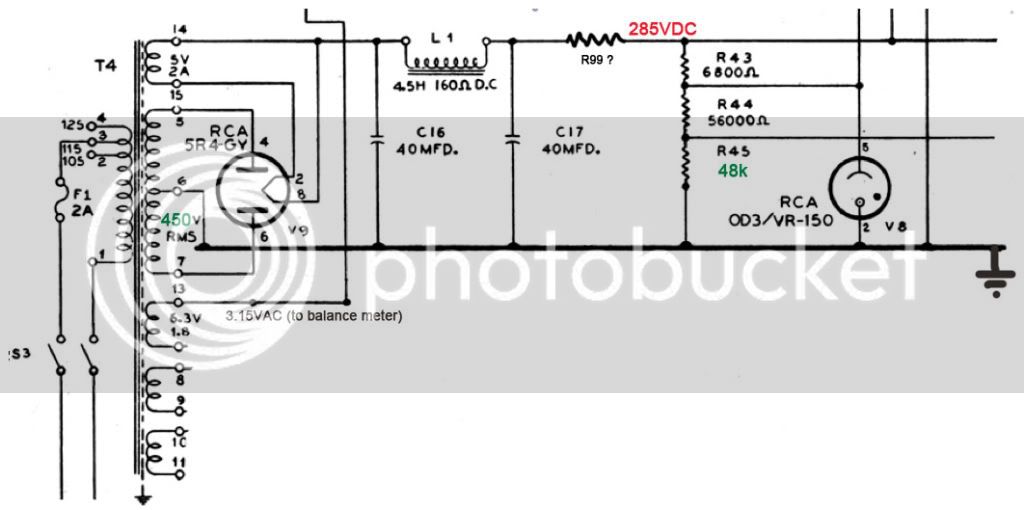
Firstly, the power supply.  I've changed it slightly because I'm going to be using a Hammond PT which has a different output to the original one used.  The Hammond has a slightly higher output so I'm planning to use a dropping resistor (R99 on my new schematic) to get to the original spec of 285VDC.  Trouble is, I'm not sure how to figure out what this value should be.  Ohm's Law should do it, but I can't seem to work out which combination of numbers I need to feed into the equation.

Other alterations I've made to the power supply are:
- Removed both 6.5VAC taps as I'm going to use 6.3VDC from another transformer (6.3VDC transformer and power supply not shown) to feed all my heaters, and the meter lamp.

- Removed C20 and R46 as I think they're to do with the hum adjust on one of the 6.3VAC taps.  Is that correct?

- Increased R45 to 48k to make up for the R46 I've removed.

- Now using a DPDT switch for the power switch.

I'd really appreciate it if someone could look over my revised schematic and tell me if I need to change it some more.  I also would appreciate it if someone could tell me how I could work out what the value of R99 should be in my revised schematic.

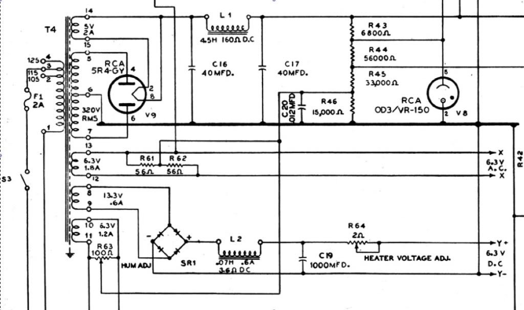
Original power supply section:
ba6a-ps-origial.jpg


My revised versions:
ba6a-ps-V1.jpg


This is the original supply
 
No, sorry I wasn't clear in my previous post (probably the Christmas day booze taking its toll!), but I'm going to run my heater on DC.  I'm planning on using an extra PT supplying 12VAC and DaveP's circuit to provide 6.3VAC to all the heaters and the lamp in the meter.
 
R46 is there to provide a positive (ca. +20V) DC bias to the heaters, in order to minimize Vkh. At idle, the cathodes of the 6SK7 are sitting at about 180V positive.
I'm curious about the smallish value of C20, which combines with R46, R33... to a corner frequency of about 1.2kHz. Instinctively, I would have put a much larger value - in the uF range.
As to R99, you have to know the current drawn, then you can apply Ohm's law. Voltage drop = R99 x I.
Current in this part of the circuit is probably about 10-20mA. Start with the highest value the calculation gives, measure the actual voltage and adjust until cooked to perfection.
 
Thanks for your reply, abbey.

abbey road d enfer said:
R46 is there to provide a positive (ca. +20V) DC bias to the heaters, in order to minimize Vkh. At idle, the cathodes of the 6SK7 are sitting at about 180V positive.
But do I need to provide a DC bias to the heaters if I'm not using the heater circuit in the schematic?  I'm going to be providing 6.3VDC from a separate transformer/ power supply.

Can you explain what you mean that the 6SK7s are sitting at about 180V?  According to the voltage chart in the BA-6A manual, the 6SK7 cathodes should be 5.15VDC...

I'm curious about the smallish value of C20, which combines with R46, R33... to a corner frequency of about 1.2kHz. Instinctively, I would have put a much larger value - in the uF range.
As I understood it, I thought that C20 was providing smoothing to the DC bias to the heaters and I wouldn't need it if I was supply the heaters with my own DC circuit.  DaveP has also omitted C20 from his power supply circuit (which I've attached to this post for reference).

As to R99, you have to know the current drawn, then you can apply Ohm's law. Voltage drop = R99 x I.
Current in this part of the circuit is probably about 10-20mA. Start with the highest value the calculation gives, measure the actual voltage and adjust until cooked to perfection.
  Great, thank you!
 

Attachments

  • 29ejc7t.jpg
    29ejc7t.jpg
    60.9 KB · Views: 97
letterbeacon said:
Thanks for your reply, abbey.

abbey road d enfer said:
R46 is there to provide a positive (ca. +20V) DC bias to the heaters, in order to minimize Vkh. At idle, the cathodes of the 6SK7 are sitting at about 180V positive.
But do I need to provide a DC bias to the heaters if I'm not using the heater circuit in the schematic?
Yes.
I'm going to be providing 6.3VDC from a separate transformer/ power supply.
It doesn't change anything to the fact that you must bias the heaters positively.
Can you explain what you mean that the 6SK7s are sitting at about 180V?  According to the voltage chart in the BA-6A manual, the 6SK7 cathodes should be 5.15VDC...
On my schematic, the input tubes cathodes are returned to the 155V supply. We may have a different schemo.
I'm curious about the smallish value of C20, which combines with R46, R33... to a corner frequency of about 1.2kHz. Instinctively, I would have put a much larger value - in the uF range.
As I understood it, I thought that C20 was providing smoothing to the DC bias to the heaters [/quote] It doesn't smooth much with this value (or maybe ther's another resistor missing?
and I wouldn't need it if I was supply the heaters with my own DC circuit.
Does your "own DC circuit provides bias too?
DaveP has also omitted C20 from his power supply circuit (which I've attached to this post for reference).
I guess that a 12nF cap whre it is connected doesn't make much difference if it is here or not.
 
abbey road d enfer said:
On my schematic, the input tubes cathodes are returned to the 155V supply. We may have a different schemo.
Ah I see now, that's via the BAL A pot (R3) right?

Could you explain to me a bit more about biasing the 6.3VDC to the heaters?  On the original schematic it has a 6.3VDC tap, but that doesn't appear to be biased at all.  Forgive my ignorance, but when you talk of biasing the heater supply, is that the same as elevating the supply?
 
letterbeacon said:
abbey road d enfer said:
On my schematic, the input tubes cathodes are returned to the 155V supply. We may have a different schemo.
Ah I see now, that's via the BAL A pot (R3) right?
More or less, yes. It goes through a string of resistors, BAL B and BAL A.
Could you explain to me a bit more about biasing the 6.3VDC to the heaters?  On the original schematic it has a 6.3VDC tap, but that doesn't appear to be biased at all.
On my schemo, C20 is 40uF. Goes to the wiper of the hum balance pot of the 6.3V EXT secondary and to two resistors across the main 6.3V secondary.
Forgive my ignorance, but when you talk of biasing the heater supply, is that the same as elevating the supply?
Same thing.
 
abbey road d enfer said:
On my schemo, C20 is 40uF. Goes to the wiper of the hum balance pot of the 6.3V EXT secondary and to two resistors across the main 6.3V secondary.

Yes but those are 6.3VAC, I'm planning to do away with those part of the power supply circuit and use 6.3VDC to heat the filaments, therefore I don't think I need any bias.  I think you only need bias is you're using AC heaters, whereas I'm going to be using DC heaters.
 
letterbeacon said:
abbey road d enfer said:
On my schemo, C20 is 40uF. Goes to the wiper of the hum balance pot of the 6.3V EXT secondary and to two resistors across the main 6.3V secondary.

Yes but those are 6.3VAC, I'm planning to do away with those part of the power supply circuit and use 6.3VDC to heat the filaments, therefore I don't think I need any bias.  I think you only need bias is you're using AC heaters, whereas I'm going to be using DC heaters.
You need bias; if not, you will exceed the max rating for Vkh.
 
What is Vkh?  I've had a Google and a search of this forum but I can't find any info at all!

Here's DaveP's 6.3VDC circuit, but he doesn't have any DC bias so how has he ducked exceeding the max rating for Vkh?

dq2ob6.jpg


I can't seem to find any info on Vkh and I'm a little lost!
 
letterbeacon said:
What is Vkh? 
Voltage between heater and cathode. Specified at +/- 90V max for 6SK7.
Here's DaveP's 6.3VDC circuit, but he doesn't have any DC bias so how has he ducked exceeding the max rating for Vkh?

dq2ob6.jpg
the cathode voltage on this schemo is only 5V. No need to elevate the heaters. On a real BA6A, the cathode voltage seems to be much higher - many resistor values are missing, so I can't tell exactly.
 
abbey road d enfer said:
Voltage between heater and cathode. Specified at +/- 90V max for 6SK7.
Ah, that makes sense - thank you!

the cathode voltage on this schemo is only 5V. No need to elevate the heaters. On a real BA6A, the cathode voltage seems to be much higher - many resistor values are missing, so I can't tell exactly.
Whoops, I actually meant to post this picture to illustrate DaveP's 6.3VDC without the bias:
29ejc7t.jpg


Attached is the voltage chart in the BA-6A manual I have, where it specifies 5.15VDC.  Maybe it's a misprint, because I can see why you're saying it would 180V.

Also, when looking for a choke, the schematic asks for 4.5H 160r DC resistance.  The nearest I can find is a Hammond one with a rating of 5H, 105r DC resistance, 150ma, 400V.  Does that sound ok?

Thanks!
 

Attachments

  • voltage chart.jpg
    voltage chart.jpg
    166.9 KB · Views: 53
The 66V on the 6H6 cathode is bias to set the breakaway point, which defines the threshold and ratio. 

The heaters are elevated to minimize noise.  A move to DC heaters everywhere will theoretically improve on this.  The original plan using DC on the 1st stage improves noise of gain reduction stage, which is much more susceptible due to dynamically changing bias conditions. 
 
for a souped up chassis you might consider the fairchild 670 pwr supply with the 3 tube regulator, very stable and you get rid of some regulator noise,

you have a pot that controls the B+ which is very handy for getting the thing dialed in,
this way the el34 takes the place of the dropping resistor,
the dropping resistor will screw up the pwr supply regulation,
you want a stiff supply that does not move for a compressor since the current draw is doing weird things,
and the more tubes, the better.
put a fan on the thing and you have a space heater.  :D

i have run into hum problems when using a aux trans for heaters, don't know why, some type of weird ground loop maybe?
 
Thanks both of you for your replies.

I am slightly reticent to change the BA-6A design too much, partly because my aim is to build a reproduction as faithfully as possible, and partly because it looks like the Fairchild power supply is going to cost more, take up more space, and more heat!

I'm trying to wrack my brains for alternatives...

The best solution would be to have a PT which outputs 320VAC RMS (which I calculate is 226-0-226VAC peak to peak) but unfortunately I'm having a hard time finding one of these.  The nearest is a Hammond which is 250-0-250 but that's still 50v over which would require a dropping resistor.

If I switched over to a solid state power supply like DaveP's above then I suppose the dropping resistor is still going to be a problem, although I assume the power supply will be 'stiffer'.

I could get a custom PT made, eliminating the need for a dropping resistor and an aux transformer for the DC heaters, but then there's the expense.


I have another question, which might seem pretty basic I'm afraid:  How do I calculate the total current draw?  On my BA-2 I used I = E/R to find out the current at the two cathodes and then added them together to find the total current draw of the amp.

In this case though it seems slightly more complicated.  For example, there are many resistors between the power supply and the cathode of the 6SK7s, including two potentiometers.  Do I add all of these together, including the total resistance of the potentiometers to find the total resistance?

The other thing is, as CJ says, the current draw is doing "weird things".  How should I account for this?

Thank you for your replies so far!
 
On the unregulated side, current is dominated by the output stage. According to the voltage chart, current is 2x40mA, so it is real class A (which is to be expected considering it is cathode-biased). In a class A stage, current is pretty much constant, so voltage drop should be constant, so no voltage sag. Still need a capacitor to provide stiff response to transients. 6V6 spec sheet shows that total current (Ip+Ig2) varies from 49.5mA at idle to 54 mA at 4.5W output. I would call it constant.
Forget about the current in the 6SK7's, since it is essentially variable (that's what makes them a variable gain cell), and why their supply voltage is regulated. There's more current in the regulators than in the input tubes. Current in R48 is pretty constant at 20mA.
Total current being about 100mA, you need 10 ohms-per-volt.
On your attached schemo, I see a choke of unknown DCr and a 330R (R47) contributing to a total drop of 65V, which suggests the choke's DCr at about 300R. This is not consistent with the "schematic asks for 4.5H 160r DC resistance" quote, unless the current is much higher than what calculations suggest, but I can't see a pair of 6V6's running at 55mA each with 260Va-k, which accounts for more than 14W plate dissipation. Limit is 12W.
This is with a rectified voltage of 340V. With the Hammond xfmr's 250Vac, the rectified voltage would be about 350V. Not a significant difference. I suggest you start with the values on your schemo and adjust under test. The actual DCr of your choke may be different so R47 should be adjusted accordingly.
 
Thanks abbey, the penny is starting to drop now.  However, I think I may have confused things slightly with posting multiple schematics.  Just to clarify:

This is MY schematic that I've adapted from the original BA-6A schematic:
ba6a-ps-V1.jpg

This is the schematic where it calls for a choke with 4.5H 160DCr.

The schematic with the choke with unknown specs is DaveP's solid state power supply he designed for his BA-6A.

I'm slightly concerned about using a dropping resistor in the circuit after CJ's comment earlier in the thread.
the dropping resistor will screw up the pwr supply regulation,
you want a stiff supply that does not move for a compressor since the current draw is doing weird things,
and the more tubes, the better.
As the OD3 is after the dropping resistor, won't that be enough to regulate the regulated supply?
 
letterbeacon said:
This is the schematic where it calls for a choke with 4.5H 160DCr.
The schematic with the choke with unknown specs is DaveP's solid state power supply he designed for his BA-6A.
Whatever the DCr of the choke, you have to make sure that the sum of it plus the additional resistor produces the desired voltage drop. I think that should compute to about 600 ohms total.
I'm slightly concerned about using a dropping resistor in the circuit after CJ's comment earlier in the thread.
I would be concerned if the output stage ran in class AB, where current draw varies significantly from idle to full blast. With a class A stage, the current is stable, so the voltage is too.
As the OD3 is after the dropping resistor, won't that be enough to regulate the regulated supply?
The regulator stabilizes the operating point of the input tubes by controlling Vg2. However, the supply voltage is not regulated. But it doesn't matter, because the input tubes act as a current generator and anyway the supply voltage won't vary much. I wouldn't worry too much since tubes are built with significant tolerance; regulated power supplies in tube equipment was a rarity, so everything was meant to operate with +/- 20% variation of the line voltage.
 

Latest posts

Back
Top