substitute
Well-known member
Hi guys! I've been out of the pro-audio world for a bit (got into guitar amps) but some friends asked me to rack-up some BA-31c's.
I've looked over a few of the threads and it seems pretty straight forward but I do have a few questions...
-The +6 gain strap isn't totally clear to me, I understand the schematic but I don't get where those points are on the actual unit.
-I think the input would be: + to pin C and - to pin E. The output: + to pin F, - to pin D. Does that look right?
-Given the fixed gain I'm thinking a hairball t-pad on the output and something on the front, like -5, -10, -15, -20 would be useful. The output T seems easy but can some one point me towards a variable input pad.
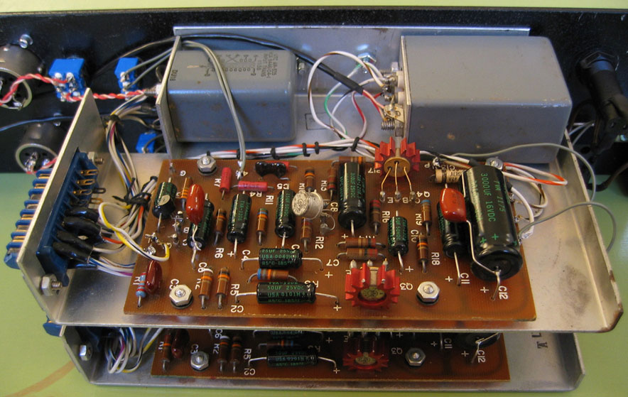
for reference:
http://farm3.static.flickr.com/2597/4149558968_b4dedc3b0d_o.jpg
Thanks!
I've looked over a few of the threads and it seems pretty straight forward but I do have a few questions...
-The +6 gain strap isn't totally clear to me, I understand the schematic but I don't get where those points are on the actual unit.
-I think the input would be: + to pin C and - to pin E. The output: + to pin F, - to pin D. Does that look right?
-Given the fixed gain I'm thinking a hairball t-pad on the output and something on the front, like -5, -10, -15, -20 would be useful. The output T seems easy but can some one point me towards a variable input pad.
for reference:
http://farm3.static.flickr.com/2597/4149558968_b4dedc3b0d_o.jpg
Thanks!