yet another green question

GroupDIY Audio Forum

Help Support GroupDIY Audio Forum:

This site may earn a commission from merchant affiliate links, including eBay, Amazon, and others.

tmbg

Well-known member
Joined
Nov 7, 2004
Messages
438
Location
Atlanta, GA
This layout has a couple caps that are big in value, small in footprint:

A bunch of 47uF caps that are 2.5mm lead spacing, and some 10uF 2.5mm

Also 0.1u 2.5mm.

What type of caps come in that footprint, but 47uF? The board layout doesnt look like they should be lytics, so what are they?[/i]
 
Considering that they're square-outline 2.5mm footprints, I get the feeling Peter had some specific caps in mind when he laid it out.
 
the .1uF are most likely the poly bypass caps for the phantom blocking lytics, i think those are the 47uf that you are looking at. i don't know though, i don't have my boards with me.
 
no, I'm talking about something else entirely. I already have those 3.5mm 0.1uF bypass polypros.

tracing the layout, looks like these 47uF's are the power supply decoupling caps for the opamps.
 
Did PeterC send you the pics of his build? That would probably answer all of your questions. :)

All the 10uF's and 47uF's are 'lytics with the Negative leg on each of them facing the switches.

I believe the .1uF in question should be a tantalum.

HTH
Daniel
 
no, I didnt get any pics. He sent me layouts and component placement, and a schematic thats slightly closer than the one on his site, but still doesnt match the layout completely.

I'll get these things built if it kills me! :)
 
Yeah, not sure why it was done like that. My guess was that Peter maybe wasn't planning on making a run of this version and was just making so he remembered what was where but since he knew what was what he didn't need the usual markers (maybe?) :)

Ask PeterC if he's still got the pics up. That really helps. Especially if you can't read a value on the board. I realized I accidentally put 10 and 10K (or some other similar numbers) resistors in the wrong spots once or twice because I couldn't read the values very well.

Daniel
 
I have a pdf of the soldermask, which is readable since there's no holes, so that's not an issue.

I think I should be good to go on these. Only thing I'm lacking at this point is switches for the HPF and LEDs for the meter. Woops, forgot to order LEDS. Ah well, I can go buy a grab-bag at ratshack :)
 
oh man, I've seen that picture tons of times and it never even occurred to me that I should LOOK at it

haha I feel stupid.
 
The silkscreened rectangular figure was a component of my own making in my PCB program.

The 47u & 10u are elctrolytics. The 2.5mm .1uF & .01uF are in the meter section, so using a high quality poly is not necessary there. I used ceramics (I think....)

Send me your email I will send you an invite to the "photo essay" which has step by step photos of the construction.

Regards
Peter
 
the PSU has been a sticking point for me for some time.

I have a +/-15V regulated supply, that's the easy part.

I've never been able to get any sort of voltage doubler/tripler to work. I ordered a 12VA 48VCT transformer, and I'm just gonna have two PSUs in one box, damn it all.
 
Thanks tmbg.

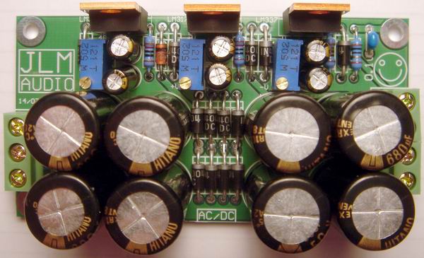
Do you think it's possible to use this PSU from JLMAudio (JLM AC/DC PCB), and power 2 channels of Peter C's Green Pre?

JLMACDC%20Built.jpg


(This quote taken directly from http://www.jlmaudio.com/JLM Power Supply.htm )
'NEW JLM AC/DC PCB below is a Linear based universal power supply with can generate 3 voltage rails from a single or dual 24 to 30vac. It has one pump charge rail for 48vdc, 1 +/- Rails that can be set from +/-2v to 37v by a 25turn trim pot. All regulators are on one edge for easy heatsink or case mounting'.

Thanks,

Steve.
 

Latest posts

Back
Top