Official C12 Clone - Build and Support Thread

GroupDIY Audio Forum

Help Support GroupDIY Audio Forum:

This site may earn a commission from merchant affiliate links, including eBay, Amazon, and others.
Is there still a plan to produce documentation for the 251 version? The dedicated thread has most of the info but just wondering.
 
Hi Matador!

What's the part number of the Lorlin (pattern) switch? Can't find it in the BOM.
And yes, I do have succeeded in breaking one.  :-X

Best,
Olle
 
Hi all.
I'm not sure if Tim Campbell reads my AMI post so I hope you don't mind me posting here.
Tim, your capsule sounds fantastic in my AMI C12.
It took me quite a long time to finish this mic but with the help of everyone on this forum and a friend who reads schematics better than I it's done and sounds wonderful.

Thank you everyone for your help and support!!
 
OK guys. I have two questions.
One is about capacitor voltages.
I see on the schematic that C12 is 630V and all the other caps are 250V respectively.
On the OPR site his BOM has this listed opposite.
His choice for C12 is 250V and all the other caps are 630V.
All the values are the same but the voltages are swapped.
What is correct? How much difference will this make?
Second question.
All the resistors are listed as .25W. Can I use .5W resistors?

Thanks as always with your help as I start this new point to point C12 build.

 
Conviction said:
Hi Matador!

What's the part number of the Lorlin (pattern) switch? Can't find it in the BOM.
And yes, I do have succeeded in breaking one.  :-X

Best,
Olle

Lorlin part #CK1454.  Mouser part #10WA364.  It's 1 pole, 12 positions.
 
aaquilato said:
OK guys. I have two questions.
One is about capacitor voltages.
I see on the schematic that C12 is 630V and all the other caps are 250V respectively.
On the OPR site his BOM has this listed opposite.
His choice for C12 is 250V and all the other caps are 630V.
All the values are the same but the voltages are swapped.
What is correct? How much difference will this make?
Second question.
All the resistors are listed as .25W. Can I use .5W resistors?

Thanks as always with your help as I start this new point to point C12 build.
Anything rated over 250V will work.  It really just comes down to availability and preference.

For C12, the lower the voltage, the bigger value you'll be able to fit (lower voltage parts are generally smaller).
 
OK guys. I have two questions.
One is about capacitor voltages.
I see on the schematic that C12 is 630V and all the other caps are 250V respectively.
On the OPR site his BOM has this listed opposite.
His choice for C12 is 250V and all the other caps are 630V.
All the values are the same but the voltages are swapped.
What is correct? How much difference will this make?
Second question.
All the resistors are listed as .25W. Can I use .5W resistors?

Thanks as always with your help as I start this new point to point C12 build.
I'm not sure which schematic and bom you're reading?? But C12 is 250v and all others are 630v in my schematic and bomb...
But since you asked...

The B+ supplies 120v so anything above that will work but you can use higher voltage caps or wattage resistors, as long as they fit :), Theoretically they should give you lower noise . The Hi z sections caps are rated at 630v when in reality they wouldn't see anywhere near this much voltage, but because this part of the circuit is noise sensitive they are a good choice.
Hope this helps.
 
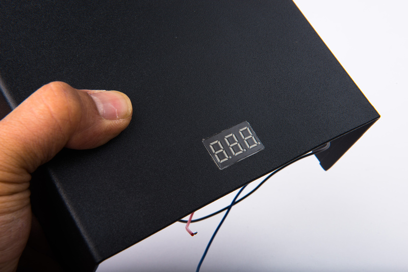
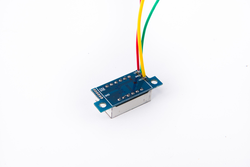
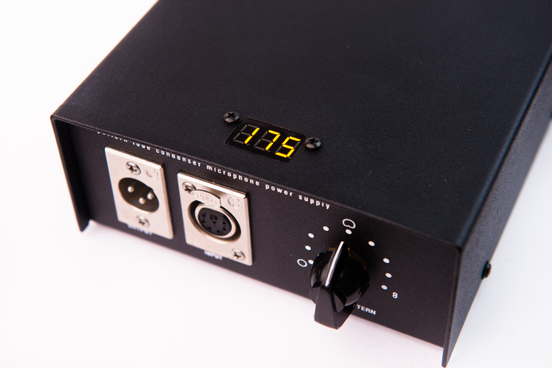
So, I was building another test microphone that will go to Christian Whitmore to test tubes on, and since I was prototyping a PSU for mk47 kits, I had a bunch of low-cost voltmeters on hand.  I thought I'd try to over-achieve a little bit and one of the meters looked like it would fit really nicely on the Alctron PSU chassis, so I thought I'd do some documentation.  So, here's the official.. .

C12 PSU voltmeter hack  :p

brought to you by the Chinese Labor Camp of course!

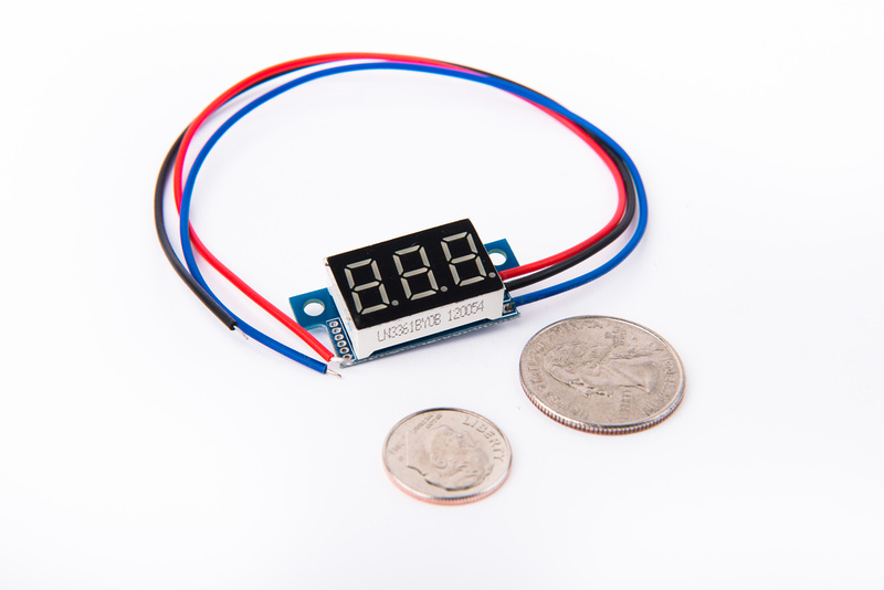
If you research these meters, you will eventually begin to circle back to the same handful of designs being marketed by a variety of brand names.  This particular one is marketed by a company called Vakind and I must admit, I bought it because the LED's were yellow.  What can I say.  Yellow has proven to be sonically superior.  That's undisputed fact.

p834889895-4.jpg


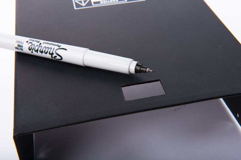
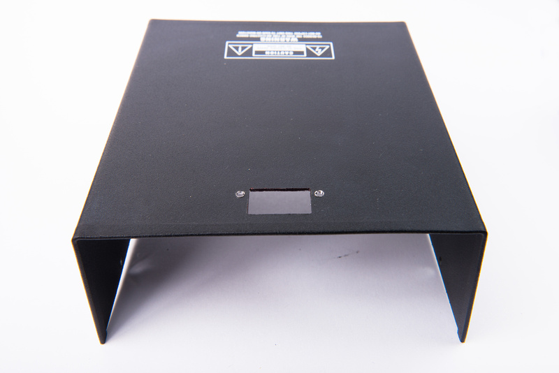
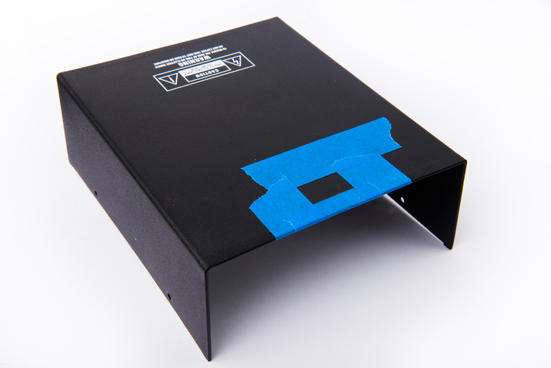
After making some measurements, I precisely mark my cutout location on the top of the case with blue painter's tape.  I mark exact dimensions knowing I will need to enlarge the hole with a file for a nice, precise fit.  Many variables will effect outcome though. . . most important is my skill with a metal cutoff wheel on a Dremel  :eek:

p987901195-4.jpg


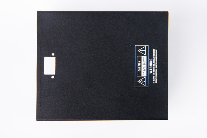
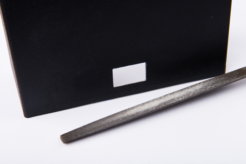
This is what my efforts yielded. . . it was pretty "exciting" trying to hold the cutoff wheel steady and inside the marked lines.  The hole is not perfect, but I thought it was pretty impressive given cave-man cutting methods employed.

p274946723-4.jpg


It ended up looking way better than my expectations :)

p12029191-4.jpg


I cleaned up the edges and filled in some cutoff-wheel mistakes with a black sharpie.

p296077869-4.jpg


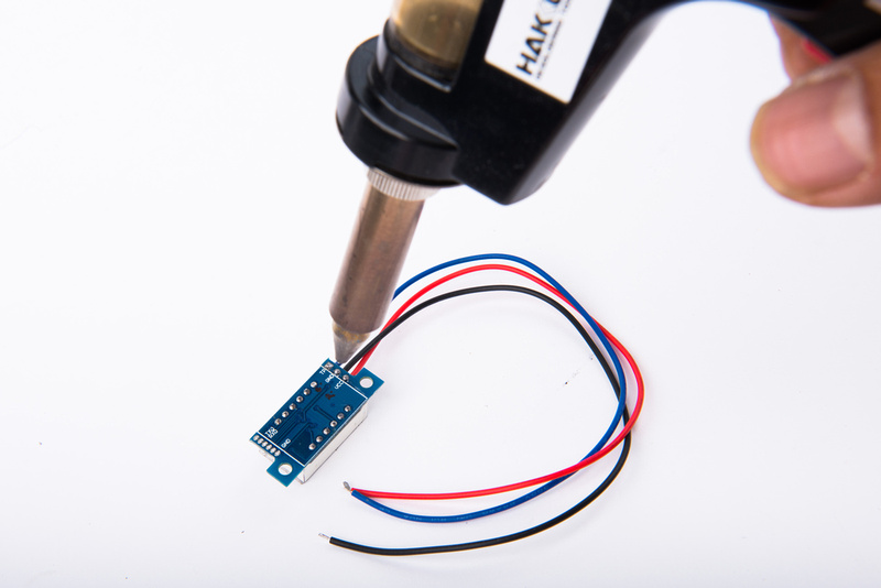
I needed to remove the factory wires to align the screw holes. . . plus, I prefer to replace them with silver teflon wire that is used throughout the rest of the PSU build, so the Hakko 808 desoldering tool makes removal very fast and easy.

p420113605-4.jpg


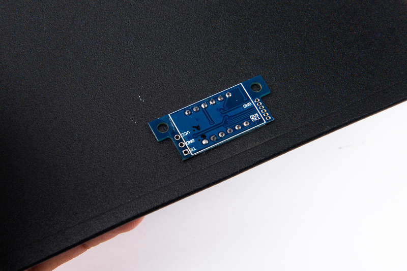
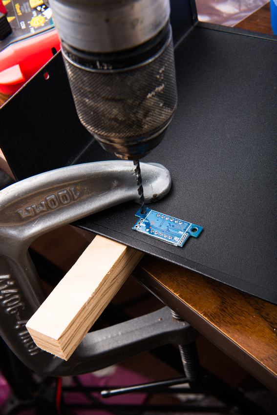
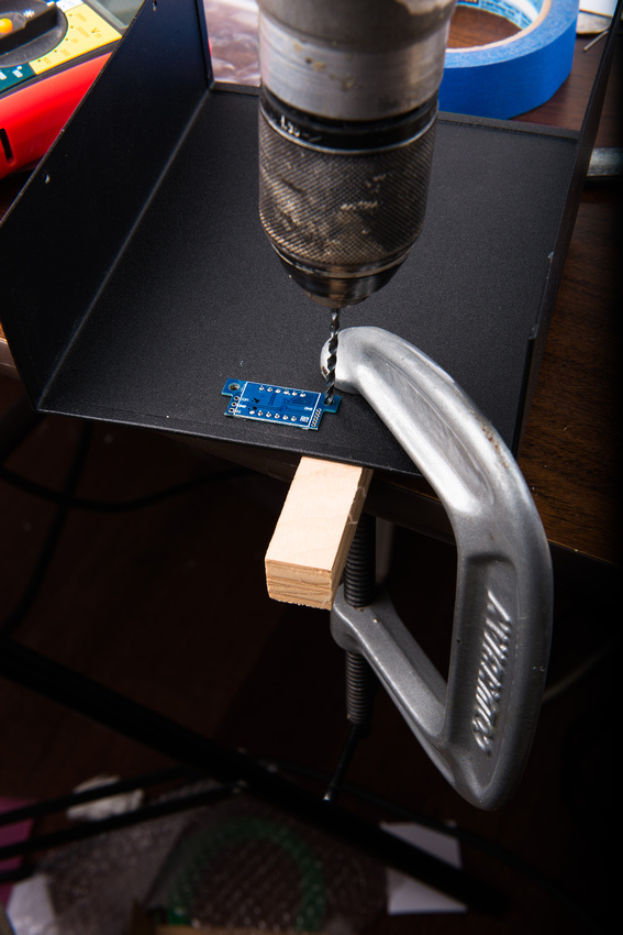
I insert the meter all the way into the hole and use the PCB as a direct drilling template to make my holes.

p32304695-4.jpg


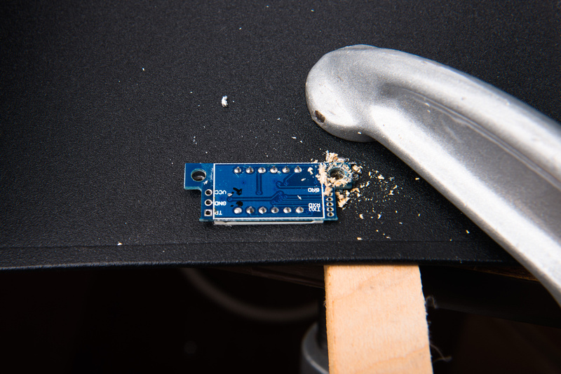
No matter how small the piece I am working on, I always find it safer to securely clamp things to my table.  A block of wood will help the drill bit make a clean hole when it goes through the metal.

p239027837-5.jpg


p73566796-5.jpg


p452975980-4.jpg


And, the result.

p322796987-4.jpg


p437543098-4.jpg


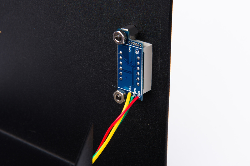
Next, I replace the wires with silver teflon wire.  I use the same colors used in my PSU build for consistency.  Green for ground, yellow for heater, and red for B+.  The meter is 3 wire and requires 4.5V-30V DC voltage for operating the meter.  I tap the regulated heater supply for this (yellow wire).  The red wire is the sensing wire that connects to B+.

p488845892-4.jpg


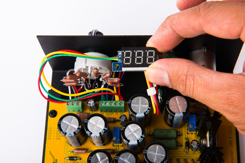
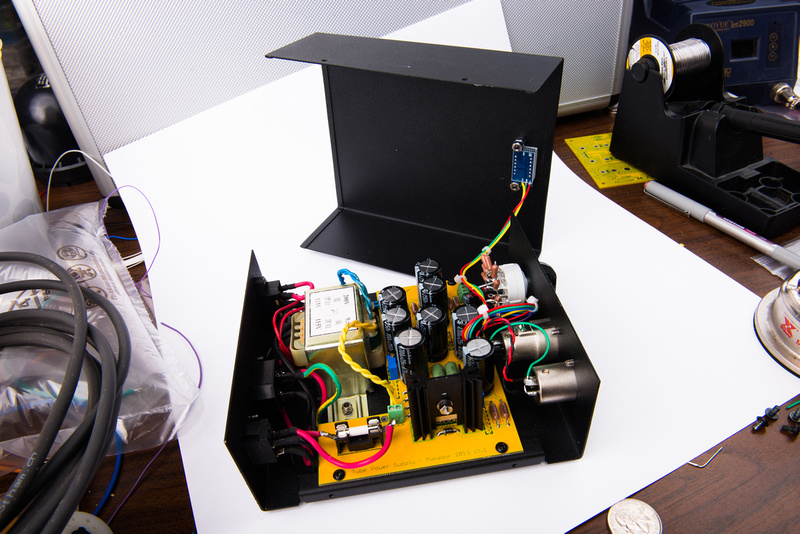
Next, I figure out how I want the cables to lay inside the PSU enclosure and attach the wires to the terminal blocks.  Enough wire length needs to be left for the enclosure cover to be removed for service with the meter attached.

p15699053-4.jpg


Next, I power up the PSU to make sure the meter is working. . . it appears to have an effect on the passive B+ circuit.  The regulated heater circuit automatically compensates, so the setting is unaffected by the presence of the meter.

p453672005-4.jpg


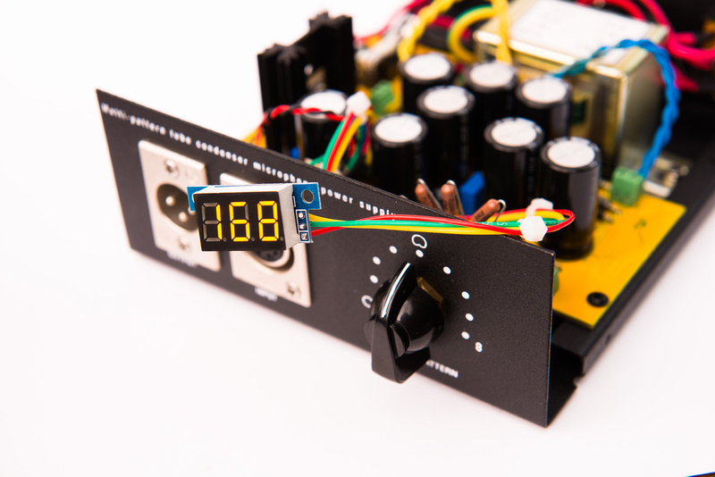
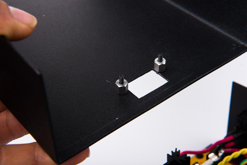
I use a couple of 4-40 black screws and 1/4" aluminum standoffs to mount the meter.

p240086456-4.jpg


p307260967-4.jpg


And, the cover can still be comfortably removed for service without removing the meter.

p154217152-4.jpg


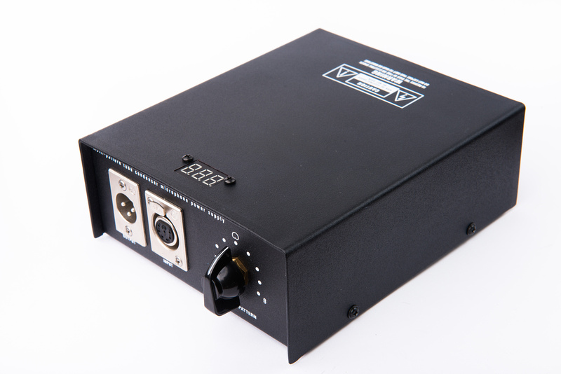
And, everything all buttoned up.

p30070993-4.jpg


p11808107-4.jpg


With the meter attached, my test microphone was only able to attain 112V DC on the B+, so speaking with Matador, he did some calculations and changing R1 and R2  in the PSU board from 91K to 68K should result in a proper adjustment range to compensate for the meter.  I will update this post with the final results after I my order arrives from Mouser.

This specific meter is off by about 1.5V and does not have a correction pot for adjustment.  The variance seems consistent, so I feel it still provides good information for the user and is certainly good enough to catch big problems should they arise.  There is another meter model in this general size for 0-200V measurement range, so I may try another meter.  I do not, however like the way the mounting holds on the other meter are laid out.  There is not enough space left for the nut.  A plastic washer would be necessary I think, but for now, I'm happy with this result.  Perhaps accuracy varies from sample to sample on these low-cost devices.
 
Matador said:
Measuring the polarization voltages is at beast approximate:  the high impedances make measure these with regular DVM's inaccurate.

For example, measuring the polarization voltage right at the PSU "P3" node will cause the meter current to drop across R11 (1 MEG).  A 10MEG meter will induce a 10% voltage error.  A 1MEG meter will cause a 50% error. :(  So a 10MEG meter will always measure 60V (the cardioid setting) as 54V due to the meter impedance alone.  120V will measure as about 110V.  The bias node "P4" has a similar problem caused by R5, however a 10% error on 1V is only 100mV. 

If you know your meter impedance you can "derate" the reading.

You can't measure anything on the capsule, because the meter current will go across the astronomically high impedances and clobber the results:  think of a 250M / 10M voltage divider:  the series resistance will clobber 97% of the measured voltage.

Well this has been a little troublesome for me. Fluke 115 DMM, 10M. B+ is 110V. In the middle of the knob switch (cardioid setting), I get: Immediately 50V, if I let it sit, goes down to 47 and stays there. Do I have a problem here?
 
barbaroja said:
Well this has been a little troublesome for me. Fluke 115 DMM, 10M. B+ is 110V. In the middle of the knob switch (cardioid setting), I get: Immediately 50V, if I let it sit, goes down to 47 and stays there. Do I have a problem here?

No problem:  the RC time constant for the polarization supply is about 2 seconds:  5 time constants is on the order of 10 seconds for the voltage to stabilize.

Remember that the polarization supply is 5M of resistance:  so adding 10M means that the equivalent resistance falls from 5M down to 3.3M.  Even this lower resistance still has a ~1.5second time constant, so the moment your probe hits the circuit it will take 5-6 seconds for the new voltage to stabilize.
 
Matador said:
barbaroja said:
Well this has been a little troublesome for me. Fluke 115 DMM, 10M. B+ is 110V. In the middle of the knob switch (cardioid setting), I get: Immediately 50V, if I let it sit, goes down to 47 and stays there. Do I have a problem here?

No problem:  the RC time constant for the polarization supply is about 2 seconds:  5 time constants is on the order of 10 seconds for the voltage to stabilize.

Remember that the polarization supply is 5M of resistance:  so adding 10M means that the equivalent resistance falls from 5M down to 3.3M.  Even this lower resistance still has a ~1.5second time constant, so the moment your probe hits the circuit it will take 5-6 seconds for the new voltage to stabilize.

Thanks for the answer.

You mentioned that it should have 54V on the pattern signal, from what should be 60V due to the DMM impedance. But I am getting 47V. Is that enough?

 
Yes you should see 54V with a 10M meter, however that assumes that the resistive divider is exactly 50% at the cardioid setting.  The resistors have an additional 1-4% error as well.

I would set your meter to resistance mode, and check the resistance of each half of the resistor string to make sure exactly half of the resistance is on the top and half on the bottom (wrt. ground and B+).  I bet you just have a few % error based on resistance tolerance for the polarization string.

E.g., set one probe to ground, and the other to the center of where the polarization switch attaches to the PCB.  You should see the resistance change as you click the switch around (from 0 ohms at one extreme to 4.7M at the other).
 
Matador said:
Yes you should see 54V with a 10M meter, however that assumes that the resistive divider is exactly 50% at the cardioid setting.  The resistors have an additional 1-4% error as well.

I would set your meter to resistance mode, and check the resistance of each half of the resistor string to make sure exactly half of the resistance is on the top and half on the bottom (wrt. ground and B+).  I bet you just have a few % error based on resistance tolerance for the polarization string.

E.g., set one probe to ground, and the other to the center of where the polarization switch attaches to the PCB.  You should see the resistance change as you click the switch around (from 0 ohms at one extreme to 4.7M at the other).

First I let the PSU sit for a while cause initial readings were strange.

Having detached the switch red and white cables from the Block,  I checked every single resistor. According to my DMM they are 400.7ohms almost all of them. In the cardioid position, it reads 1.603M. One full side 0ohm, the other side 3.205M.

The testing procedure you suggested was not consistent, the readings were changing too much.  I did this with the red and white wires connected.  (I used the same Colors as you). I am attaching a picture for reference.

Unloaded, B+ is stable at 204.5V. Pattern in cardioid starts at 99 then after 10s, it stabilizes at 86.7V. Fig 8 starts at 197, stabilizes at 184.4V. Omni starts and stabilizes at 0.08V after a long time (would probably keep going down, but took minutes to go there).

My poor electronics knowledge says that polar signal is having some extra impedance in the PSU itself?  :-X
 

Attachments

  • 20140725_034721.jpg
    20140725_034721.jpg
    205.7 KB · Views: 28
Matador said:
Are you probing where the grey wire attaches?  Or where the polar signal goes out to the microphone?

Black lead: P6 screw (output block). Red lead: Center polar switch block screw, (grey cable, middle one). In omni, I read zero ohm. As soon as I flip the switch to the next step to the right, starts changing readings. After 10s, it settles to 343Kohm. Next switch move is close to 600Kohm. Next goes around 777Kohm. Switch in cardioid is around 860Kohm.  :eek:
 
barbaroja said:
Black lead: P6 screw (output block). Red lead: Center polar switch block screw, (grey cable, middle one). In omni, I read zero ohm. As soon as I flip the switch to the next step to the right, starts changing readings. After 10s, it settles to 343Kohm. Next switch move is close to 600Kohm. Next goes around 777Kohm. Switch in cardioid is around 860Kohm.  :eek:

This all sounds correct:  does the microphone sound bad, or is the pattern switching not working correctly?
 
It works. Other than having a one side of the mic that sounds so different from the other one in fig8 (more bass on one side), it works (Capsule differences maybe? Tim Campbell capsule here). So you think is fine? What is happening with those 47V then? Would that affect cardioid´s pattern ability to reject backside or room sound?
 

Latest posts

Back
Top