EZ Tube Mixer Support Thread

GroupDIY Audio Forum

Help Support GroupDIY Audio Forum:

This site may earn a commission from merchant affiliate links, including eBay, Amazon, and others.
Good day Ian and Holger!
 
    I have been experiencing the same problem but i get to power 6 modules before the problem gets very bad.....that's one of the reason i scaled down my project!(also $ and space)  I was kind of waiting on you guys with more experience to see if it was something wrong with my build since i'm not very experienced myself.  So today is a great day!!!
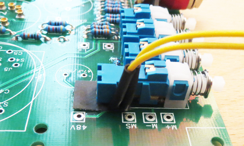
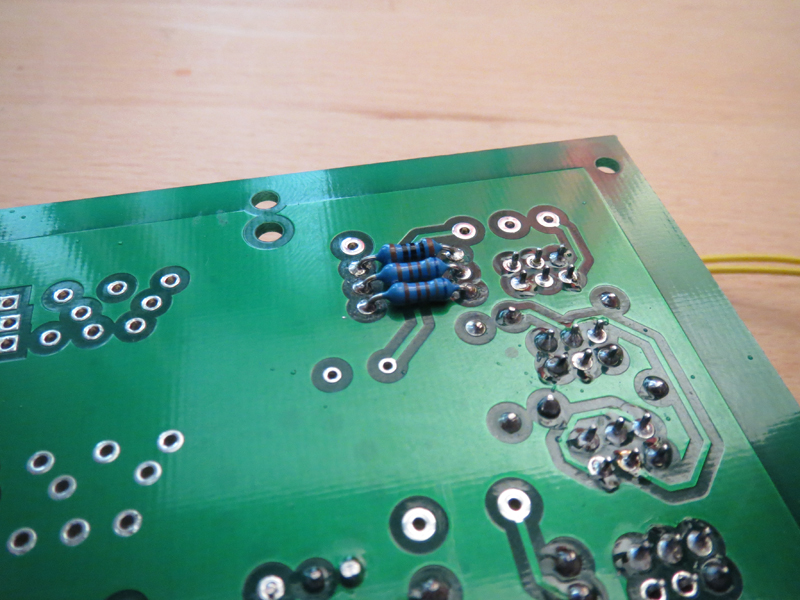
Could i bother you or Holger to post a picture of how you installed the decoupling cap? From HT+ to 0V ref?


Regards!

Pierre
 
Hi Pierre,

Here is a picture showing how I connected the extra decoupling capacitor in the EZTubeMixer demo. As you will see I am using the two module motherboard and the are two pads labelled 300V and 0V that you can use to fit the capacitor. I only fitted it on the top side of the PCB because access the the underside of the PCB is difficult. If you can get to the underside of the board then it would be best to fit it there.

If you are not using the two module motherboard then there are two options. If you are using a 6 module motherboard then you can add the capacitor across the pins of the 32way connector on the motherboard. You should only need to do this every other connector. The other alternative is to solder the capacitor right across the 32 way connector of the EZMixer V3 or Twin Line Amp board in which case it makes sense to add one to every board.

The value of the capacitor does not seem to be critical. Holger used 10nF and I used 220nF only because that was what I had to hand. Whatever values you use it should be a 400V film capacitor. 100nF is probably a good value which is available from many suppliers.

Cheers

Ian
 

Attachments

  • HTdecouple.jpg
    HTdecouple.jpg
    450.1 KB · Views: 55
I always wanted an LED indication for the 48V, so I did a little mod on the amp card.

I used a PHA4UEE instead of a PHA2UEE switch, cut off the additional legs except for the two I need for the LED, moved three resistors to the back.

switchmod.jpg


resback.jpg

 
Holger said:
I used a PHA4UEE instead of a PHA2UEE switch

Sorry for the off topic but comparing the Toneluck and the ALPS switch I found that I prefer the "feel" of the tone luck. The ALPS is a bit too "soft" for my taste when you "push" the switch. How the C&K compared to the Toneluck and the ALPS? Hope I make some sense  :)
 
Hi Ian,

PCB's arrived today ;)

So i start collecting all the materials together now.

Colin told me that he is actually low on the VTB9043 (probably back in stock in a couple of weeks), which i need for the REDD+HELIOS EQ.
I started looking at the schematics and see that only 1 value is coming from VTB9043 on both pcb's. Right?

(Helios) 10H VTB043 to PAD E
(REDDEQ) 7H VTB043 to PAD D

Can i substitute these two values with a axial leaded conductor?

Thanks, Sven
 
dipfrik said:
I started looking at the schematics and see that only 1 value is coming from VTB9043 on both pcb's. Right?

(Helios) 10H VTB043 to PAD E
(REDDEQ) 7H VTB043 to PAD D

Can i substitute these two values with a axial leaded conductor?

Thanks, Sven

Yes, it is the same inductor on both boards and only one tap is used on each. You can use another inductor if you wish. I am not sure if you will find a 7H or 10H in an axial lead format but if you do then let me know. The original Helios used a winding on a Parmeko transformer so the exact construction method is probably not that important.

Cheers

ian
 
jhulk said:
i looked you can get 10h but for 7 the nearest is 6.8 in the axial versions

Are you absolutely certain these are 10 Henries and not milliHenries? Can you provide a link to them?

Either way, 6.8 Henries should be fine as a substitute for the 7 Henry one.

Cheers

Ian
 
I think 10μH != 10H ;)

Based on my research it's nearly impossible to find 7H or 10H as single value.

Cheers, Sven
 
i was having a total blonde moment

1 henry is 1000000uh

why i thought it was 6 digits rather than 7

i checked with the henry calculator doh and saw it was seven

hammond do them but they are chassis mount

 
jhulk said:
i was having a total blonde moment

1 henry is 1000000uh

why i thought it was 6 digits rather than 7

i checked with the henry calculator doh and saw it was seven

hammond do them but they are chassis mount

Ah well, never mind. If you look at the REDD EQ design you will see those axial leaded inductors used for the brilliance control.

Cheers

Ian
 
Nice build Holger. I think this also illustrates the advantage of using the Fischer modules. It moves the PCB to the right which means there is a lot more room to place the legend around the gain control and, as you have done, you can even get the button legend on the left instead of the right.

Cheers

Ian
 
Great work Holger! You are adding all the details that will add flexibility to the sound, it's gonna be one hell of a mixer!
 

Latest posts

Back
Top