RCA BC-2B tube console restorations

GroupDIY Audio Forum

Help Support GroupDIY Audio Forum:

This site may earn a commission from merchant affiliate links, including eBay, Amazon, and others.
Referencing the mix input query here:

https://groupdiy.com/threads/rca-bc-2b-tube-console-restorations.53576/#post-694136
Work delays sometimes provide clarity. I'm thinking rather than using (2) 230R to raise mix input Z to 600, that the hot side should get 150 and the ground side 300. That should provide a ground reference and load of 300R to each leg of an electronically balanced source, and maintain the same pad/Z-change as planned previously. Mo' betta I think!
 
Last edited:
First panel is finally here.  You can see how tight the height clearance is.

12390208653_993b1fa4e0_b.jpg


12390066115_4eacf6aa82_b.jpg


Panel totally wired in, down to double checking that overall it's wired '1 studio' rather than '2 studio', and rewiring the MON amp for correct Z in that case.  Then hopefully final testing, no other gremlins.  Might manage a recording session with it later in the week. 
 
Wow, Doug - what a project - AWESOME!

I have the Aussie equivalent, the AWA BCU-1 (must be licensed design from RCA - looks literally essentially identical).

Would be keen to know how you've gone with this console, in action, in subsequent few years since completion.

Cheers!
Evan
 
Missed the last post somehow. 

Lots of radio station mods were found and undone.

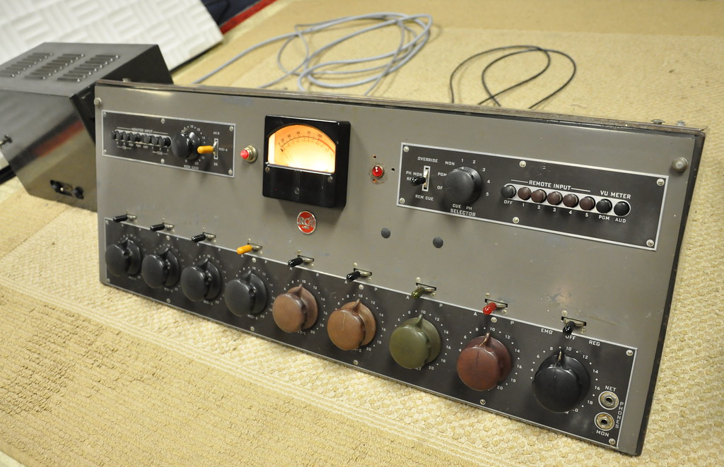
Mix bus resistance changes worked out fine, as planned.  Bus losses are now roughly 26dB.  Patching line in to the busses from a +20dBu FS converter still requires the channel faders and bus faders to be set fairly low, and there’s not an obvious noise penalty from the new bus loss figure when using the console stock PRE -> PGM.  Spec for S/N is still met, according to my AP test set. 

PGM is 84dB max.  MON gain is 95dB max.  Noise is primarily dependent on the 1st stage 12AY7, so selection is important with all that gain.  I got the two amps reasonably close to one another for matched gain setting in that regard. 

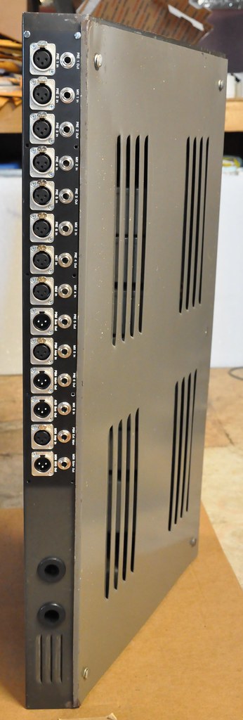
You can do a dual mono mix using PGM and MON amps as the two output amps.  You can also go line in to the busses and take them back into a pair of PRE inputs and take their direct out, to use a more symmetrical pair of output amps.  I’ve printed mixes both ways, and the PRE’s will feed a mix into +24dBu FS converters with healthy level and no detracting distortion; I’m sure THD % is high in the low frequencies if you measure it. 

When taken direct out the PRE have some high treble boost from unloaded output condition, so there’s more ‘air’ than when loaded 600R within the normal console flow. 

Obviously if you use it as a mixing platform, you can structure DAW outputs such that you get true stereo by spreading across DAW outputs.

Converting these to LCR stereo isn’t realistic, given the lack of needed contacts across all channel switches.  As a stand alone live tracking platform with mono source mics it’s mono or dual mono (L/R). 

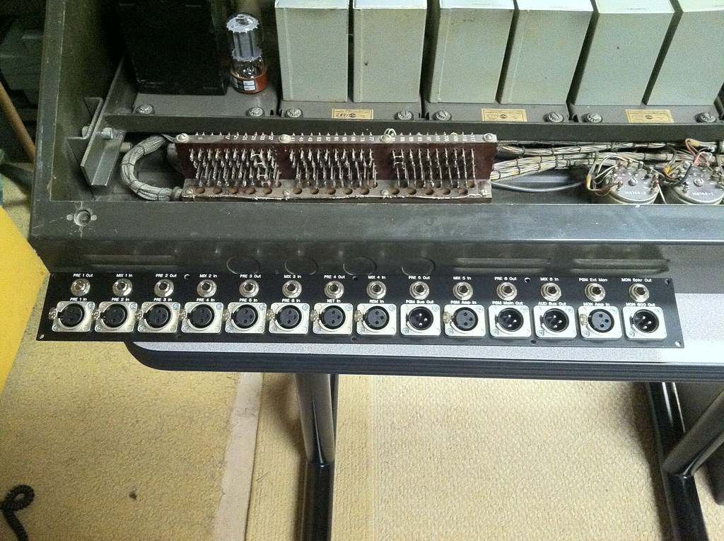
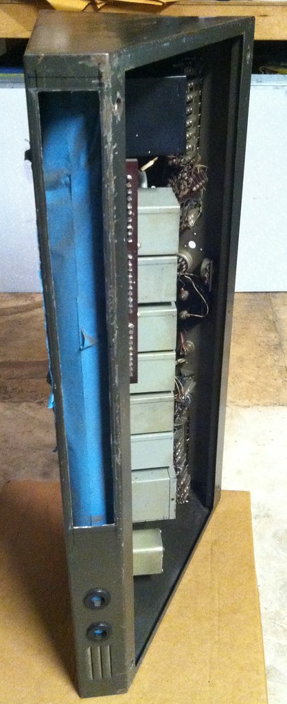
This really is the height of options with RCA tube consoles, the final BC-3/5/6 series use Hi-Z mixing and don’t provide any patch points for breakout.  This is the most modular console RCA made in the tube era.  BC-5/5/6 have internal PSU’s, which has to have a noise penalty in practice. 

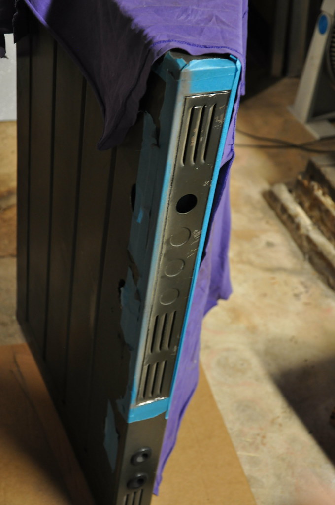
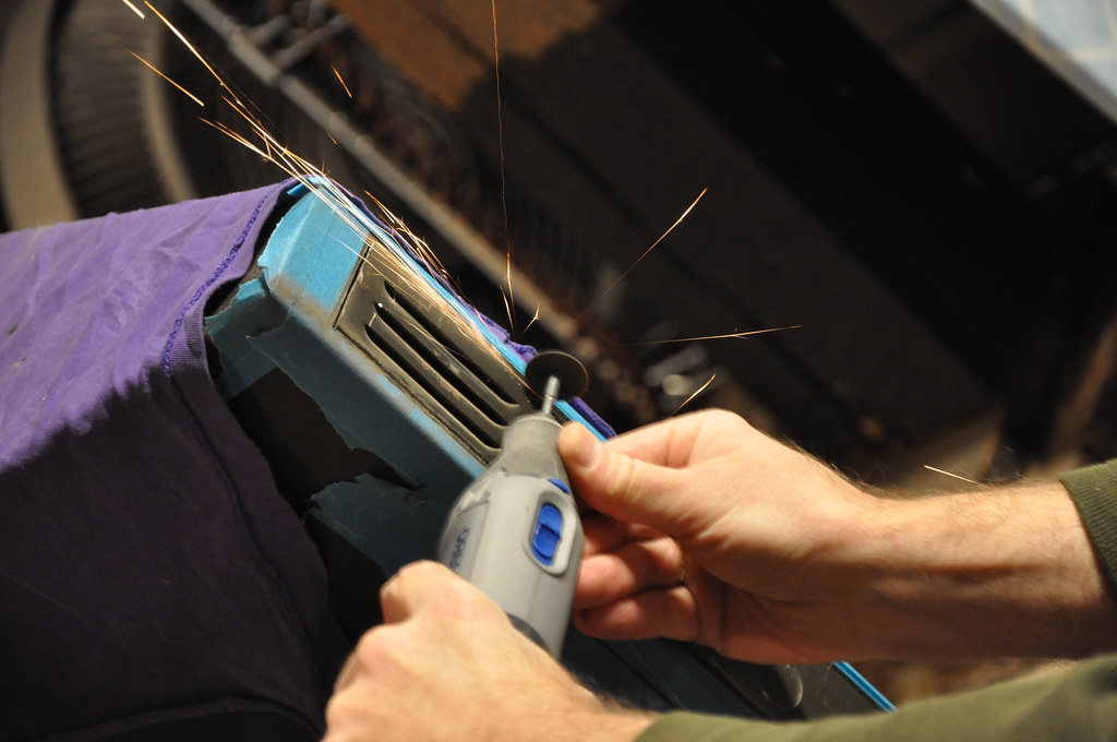
Oh yeah, added some metalwork inside to put 3 position NFB gain mod switches on the PRE.  Roughly -10/stock/+6. 

There’s an interesting design aspect I haven’t noticed in other similar consoles.  The busses are unbalanced like all US broadcast mixers were.  Except the PGM and MON amps have been balanced relative to the mixing busses by grounding their input center taps, and feeding half of the mix bus inputs to one side of their input transformers and the other half to the other side.  In my tests I found leaving that CT ground connected on the PGM amp lowered hum components by 3dB, but in the MON amp 60Hz dropped by 14dB with the CT floated.  There may be a loop formed in this particular console with both grounded, since they have separate B+ feeds and differing current draws across the common B-/GND. 

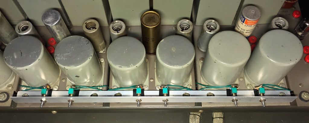
I’ll semi-confirm my suspicion that the ancient erroneous B+ value listed around the interwebs for the PRE of 360ish VDC is the result of using the original PSU with the MON amp disconnected.  All B+ voltages come off the same resistive network, so any change on one branch makes the others swing.  Even seemingly minor resistive variances from the listed values cause appreciable B+ swings given the current.  In short, don’t fire one of these up without real attention to the operating voltages, knowledge that all amps are connected to power properly, and good working tubes are in all slots.  The first part is tapping the primary of the power transformer to the correct voltage; it may be set for 105/115/125 AC.  A Variac won’t be your friend much either, as the (3) 6V6’s really don’t operate properly with much of a filament voltage drop, though most preamp tubes are unaffected by low filament values, like 75%.  If you fuse the relay portion of the power supply and have rebuilt it replacing the selenium rectifier with silicon, you'll need to add series resistance and ideally tap the AC input at 125VDC to account for the expected selenium losses. 
 
Doug do you like the sound of the pre direct outs without a 600 ohm load, going into a higher impedance convertor input (if that's what it is) ? Is it a subtle  high boost would you say ?

I'm wondering in general if it's good to have the option available. I am into fixed gain amps and sometimes I have the choice of having a 600 ohm attenuator wired to the output in the same box or using an external atten panel or faders.
 
As you may know, preamps like this are very reactive to their mated circuits, so it' s not a simple answer.  If you have to use a 20dB pad up front that also creates a treble rise, so loading becomes important.  I keep lots of inline barrels around for input pads and output loads, use as needed.  If it's a droopy ribbon on a loud source, you might need the input pad, and want to leave the output unloaded just to flatten the overall combined response. 
 
That's very interesting, I didn't know that padding the front would increase the treble. Sounds like it would be wise to preserve the option to go unloaded in some cases. I'll have to play around with it. I've been padding the inputs just for gain staging as needed and always keeping a 600 ohm attenuator on the outputs even if it was doing no attenuation.

Thanks.
 
You really have to look at any preamp type with an analyzer, and then read between the lines to suss the possible changes with an actual transducer signal.  I think my RCA preamps thread which has a lot of plots of various types shows some with and without a resistive input load, and some transformers make a treble peak with a resistive shunt up to and over 1K ohm, which proves you can't really fight the effect.  I see the same effect with lots of older tube units.  It's never huge, and always fairly high up, so it tends to sound like a smooth air EQ addition.  I can imagine it getting harsh with a bright condenser that's in itself pushed pretty hot. 

What sort of 600 ohm output attenuator are you using?  That's a whole other can of worms, with effects dictated by the actual output Z of the preamp. 
 
For attenuators right now I'm using 7 rotary 600 ohm ladder attenuators. They are stepped, but smooth turning in between steps, 2 db per.  I've been using those with UA and Altec solid state pres, but going forward those will be for my fixed gain tube preamps, and anything extra that might come up like makeup gain or daisy chaining two pres with some reduction in between.

In a week or so I'll be picking up a freshly racked bank of 10 600 ohm faders, they're Altecs which are bridged T circuits. Those are going to go on the outputs of my UA 1108 modules. I think my tech found room to include 2 more Duncan 600 ohm faders as well (341 DA 2Q) which will be spares.  Does that suggest anything of concern with those pairings ?

I tend to avoid real bright sounds and I consistently favor dynamic mics and ribbons. When I use condensors they are usually  darker to medium bright ones (KEL HM1, PML DC-63, and Blue bodies with M7 and B7 capsules). Sometimes I use Beyer MC930 or old 451s with CK1 or CK2 so I'll maybe be more watchful of padding on those. I would guess that using the onboard pad on the mics would have the same treble rise as doing it after the mic ? Or is it different if the pad is between the capsule and the amplifier circuit in the mic ?

thanks again.
 
600 ohm ladders have a minimum 6dB insertion loss due to series Z, though you can wire a separate switch to make them 0dB insertion loss, using them purely as a load resistance. 

Real T types are actually a variable load resistance by themselves, and only act properly with a 600 ohm shunt resistor on the output side or a true 600 ohm input after.  A real one truly goes to 0 insertion loss and goes open on the shunt at that position.  A modern CAPI/Hairball type does not have true T resistance curves, and presents a lightest load value of about 1K, so they really don't need / shouldn't have a separate shunt resistor.  If you shunt one of those they drop down as low as 300 ohms with significant attenuation, I  recall.

Some amps are sensitive to the loading effects, some really aren't. 

The onboard pad on a condenser wouldn't have an external effect. 
 
Cool. I'll talk to my guy about the 600 ohm shunt resistors for the faders.

Since you mentioned real T circuits, I'm wondering if I am correct about those ? The Altecs are  SM8272-01gg

there's a circuit on their case (this isn't one of mine but same model)

http://i.ebayimg.com/images/g/H1wAAOSwfVpYweVG/s-l1600.jpg

and it's also represented in the upper left of a system diagram on page 18 (going by the PDF page numbering) of this groovy console manual

http://steampoweredradio.com/pdf/altec/altec%20model%209200a%20console.pdf
 
Those are ladders.  900-315 ohms to ground on input side, 315-900 ohms series, constant 585 ohms output to ground. 
 
Ah, great, that makes things simpler. I'll just have him check the Duncans then and add the shunt resistors on those if they are Ts.  Might be handy to have those on call if the insertion loss of the ladder faders is ever a gain staging problem.
 
Here's the metalwork inside to put 3 position NFB gain mod switches on the PRE's.  Roughly -10/stock/+6.

-10 begins to show some 7Hz boost, so at the limits.  Gates did that sort of thing on purpose.  -6 shows more bass loss, as NFB is required to drive the output transformers properly.  Both of these options add flexibility at the cost of some change in response, I think acceptable in practice.  When combined with an external input pad, there are a lot more gain options.   

Even this almost won't fit, it barely leaves clearance for the front panel bus switches when closed, and barely clears the top when swung open.  There's definitely no room for a footprint like a rotary with more steps.  You wouldn't want to take it to the front panel with new holes drilled because of the wire length....and you don't want to be that guy and drill new holes in 65 year old equipment either. 

36056360152_8ae6d89245_b.jpg
 
Noticed something else in my notes: 

I've burned in several sets of 12AY7's for 40 hours or so, which are the 1st gain stage in every amp.  The samples burned in PRE's are quieter than the samples burned in either PGM or MON amps.  PRE samples moved to PGM/MON maintain a lower noise floor going forward.  PRE's are much lower current, while PGM/MON are run more as power stages at higher current.  My slight amount of evidence suggests lower initial current makes a quieter tube for the long term.  Those noisier PGM/MON burned tubes are much quieter when moved to a PRE, which may be fine if the PRE will only be used as a standalone PRE without further gain, as it would be in the original console structure. 
 
Wow Emrr ,
Thats a serious restoration job you've done with those RCA's . I have a meeting tomorrow about the possible renovation of an old Marconi tube mixer . If I get the job I may have a few questions along the way that you could help me with .
Looks like input ,interstage and output transformers were the order of the day way back then ,judgeing from the amount of iron in there .
I picked up one of these a few years back ,dates from the mid 20's
http://www.valve-radio.co.uk/gallery/marconiphone-a2-amplifier/
Originally battery operated ,sadly only one of the original transformers left in place ,Im hoping at some point to bring it back to life again , maybe as a mic pre. Id like as much as possible to use components from the era ,but solid carbon rod grid resistors are hard to find, so a balance will have to be struck between originality and availabillity.


Latest posts

Back
Top