Cascade Modules in GDIY 51X Rack

GroupDIY Audio Forum

Help Support GroupDIY Audio Forum:

This site may earn a commission from merchant affiliate links, including eBay, Amazon, and others.

bruce0

Well-known member
Joined
Jan 24, 2010
Messages
1,065
Location
Boston
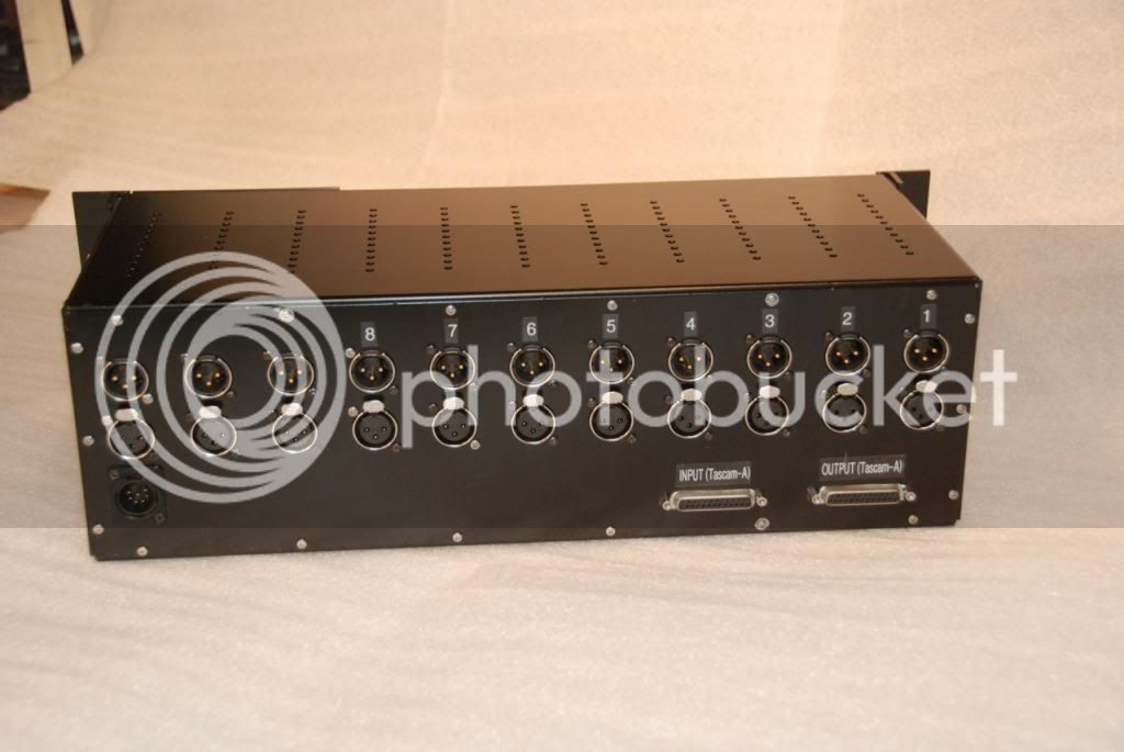
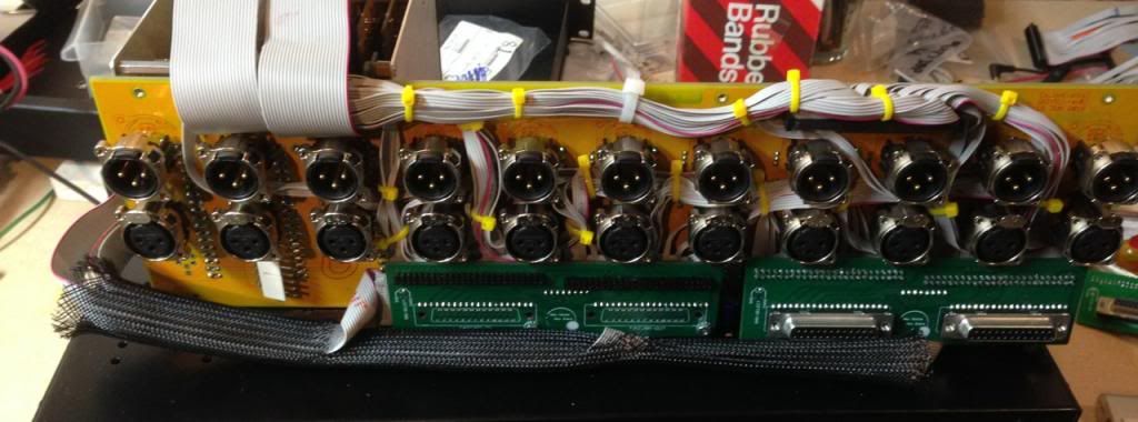
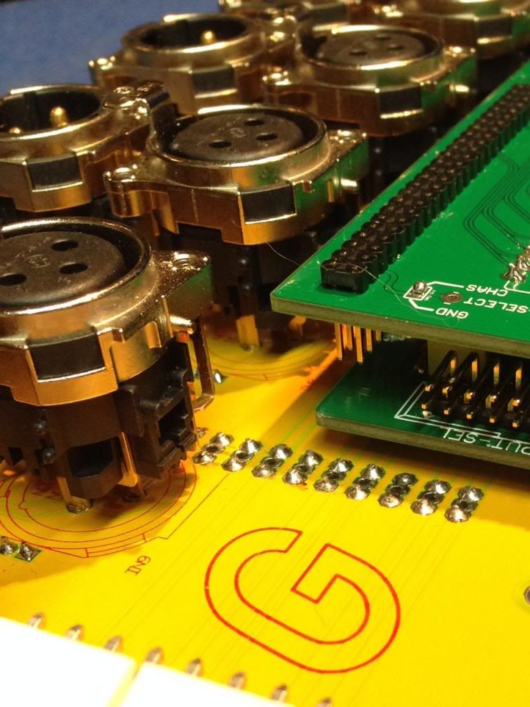
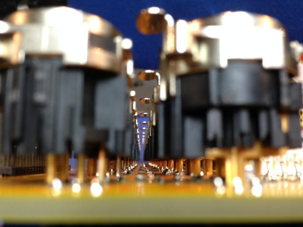
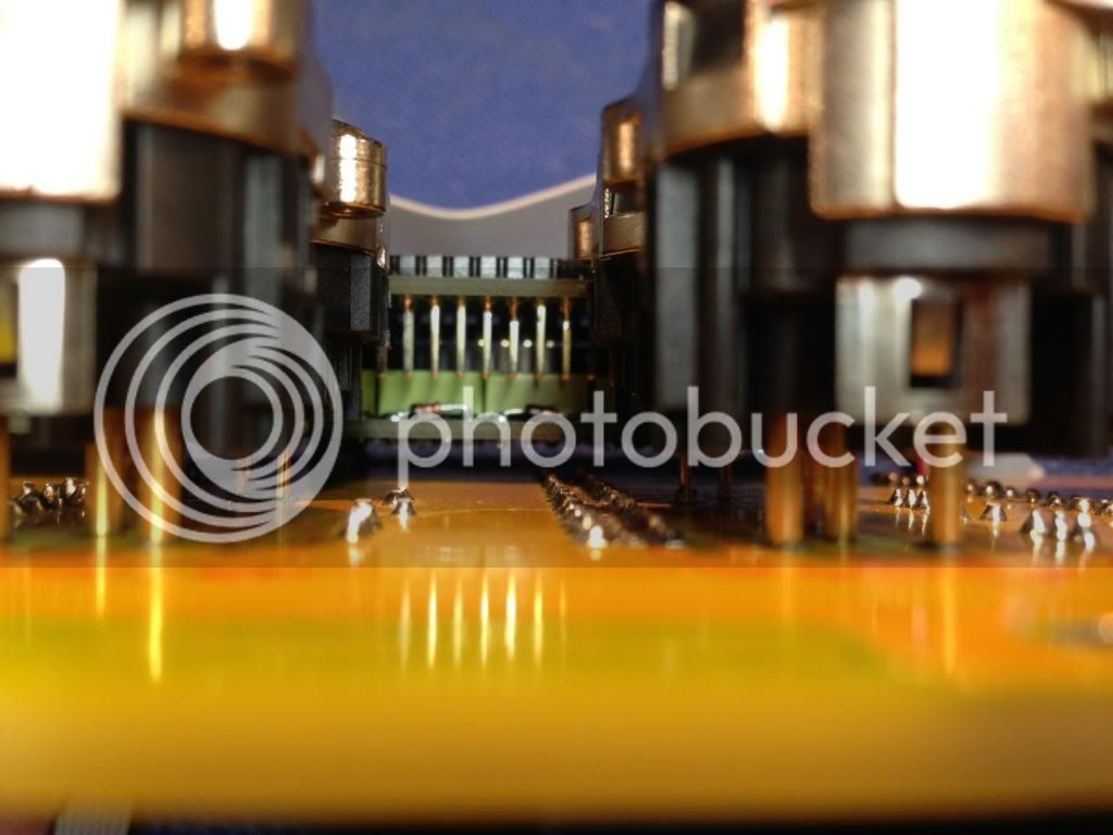
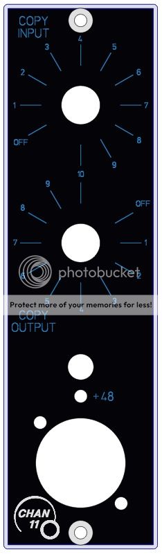
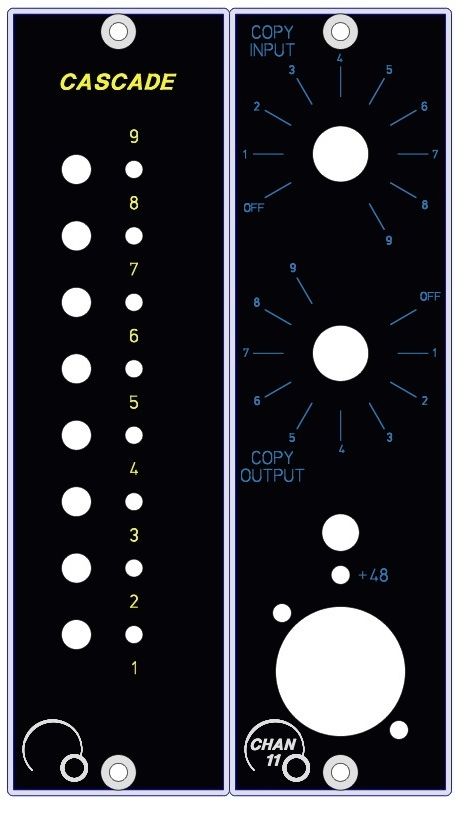
I thought I would prototype a card (2 cards actually) to allow connecting a 51x module to the next module in the 51x rack.  To keep the signal path short, and the wiring easy, I did it with relays.  The whole card fits in the space under the XLR connections (just like my TASCAM adapter ... It is the same size).  I have to lay it out again because I want to use standoffs and the holes in the 51x backplane (Or I could mount this one with standoffs off the metal back). (By the way.. does anyone know (Volker) if all the versions of the 51x Rack backplane use the same hole spacing?  The holes are never used, so I am worried about them going away).

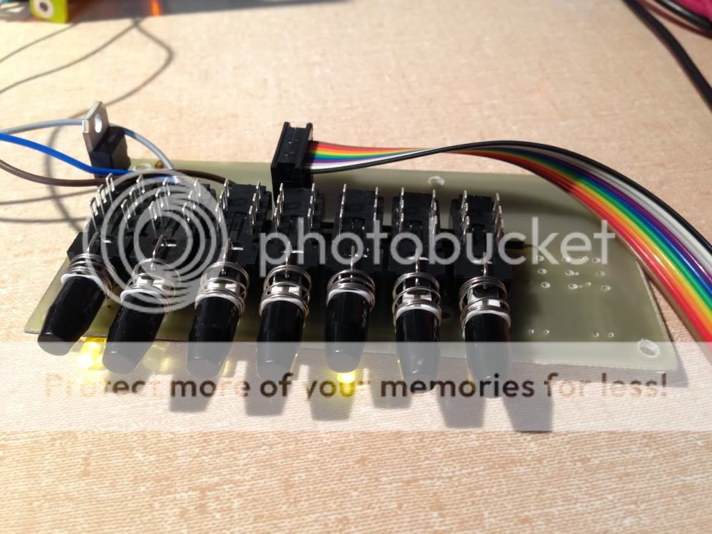
Anyway it works, and it is kind of cute. 

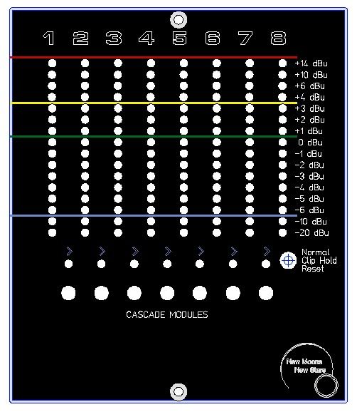
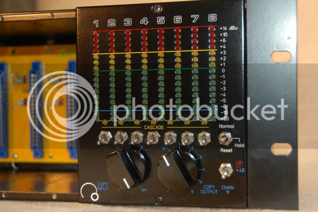
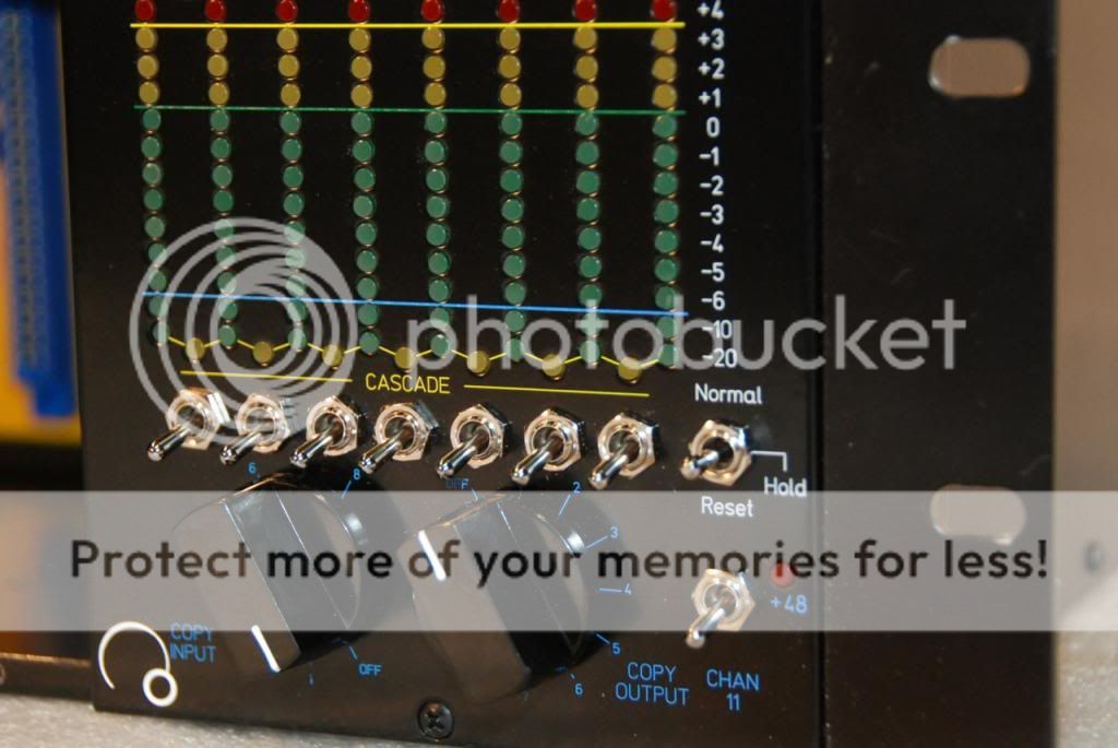
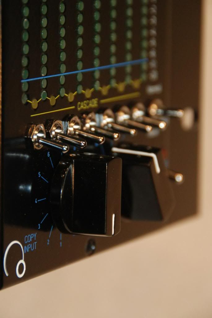
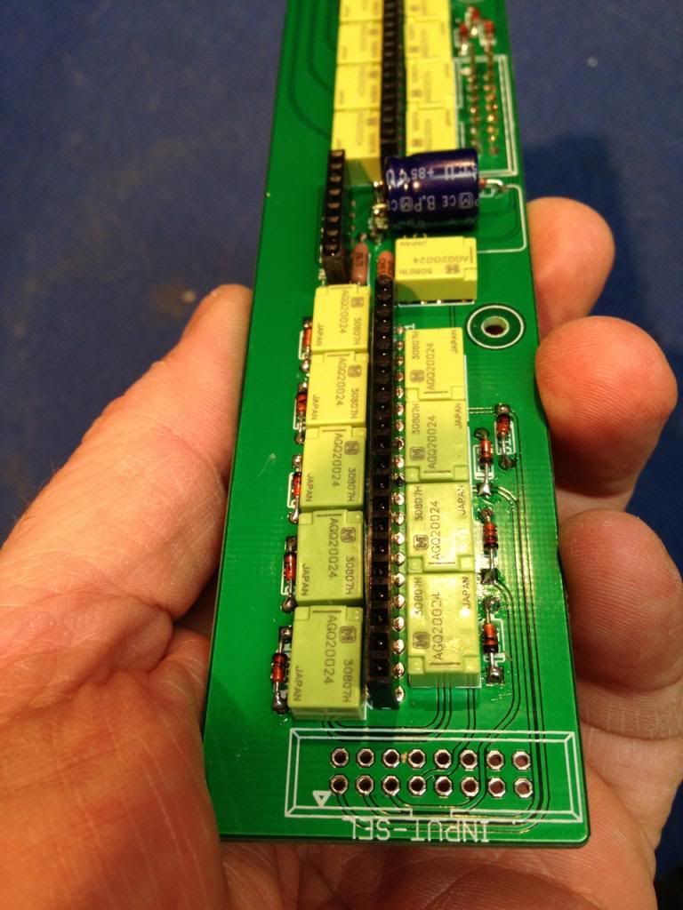
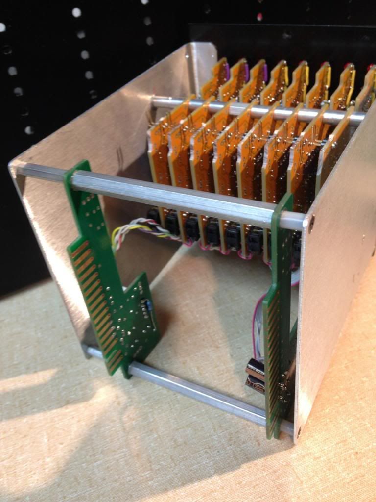
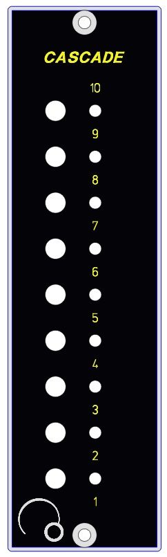
Uses +16V for the 12V relays, but uses -24V for the LED's because there is lots of -24V unused). I am putting this one into my 8 channel meter so I am only using 7 switches and relays (because there are only 8 modules when I fill three slots with a meter) but it is capable of routing 9 modules to the next module (1-out to 2-in, 2-out to 3-in, etc... finally 9 out to 10 in.) and the switch card will fit vertically in a single module so a simple 1 module switch front is possible (in slot 11).

null_zps173b23c6.jpg


null_zpsed6638f8.jpg


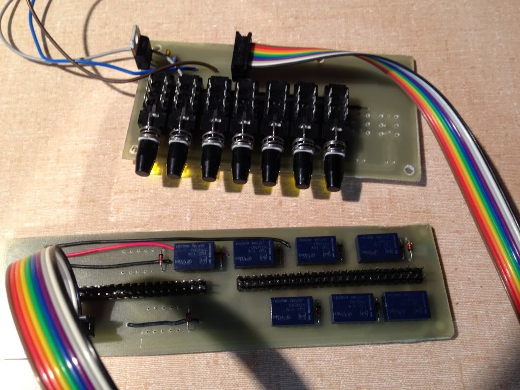
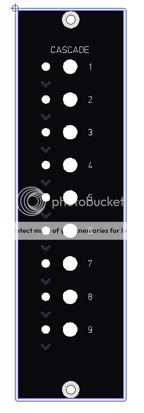
So it can do this simple switch front plate (might need studs on back of the faceplate - or screws to hold the carrier)

1module_zps0c8add4c.jpg


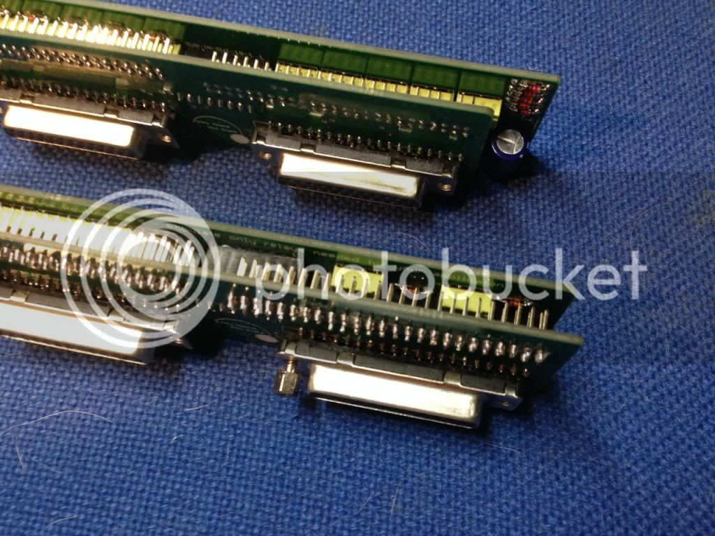
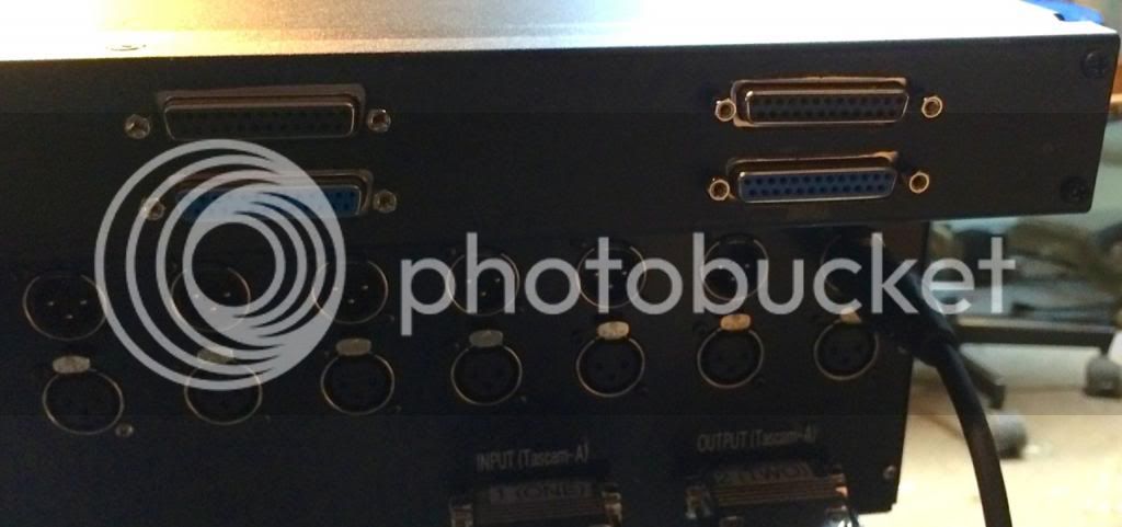
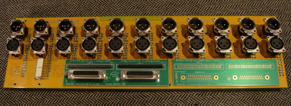
The relay card fits in the same place that the tascam adapter does (the left one probably).

DSC05847.jpg


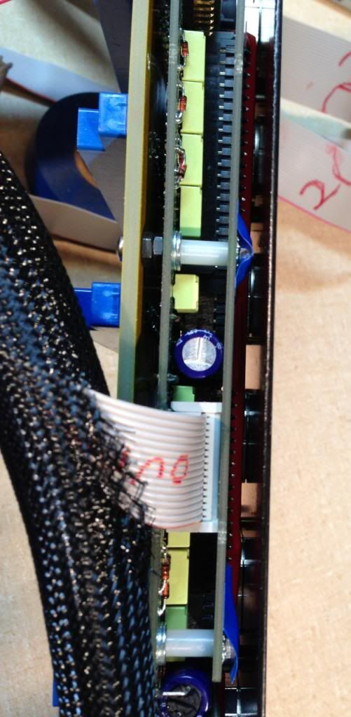
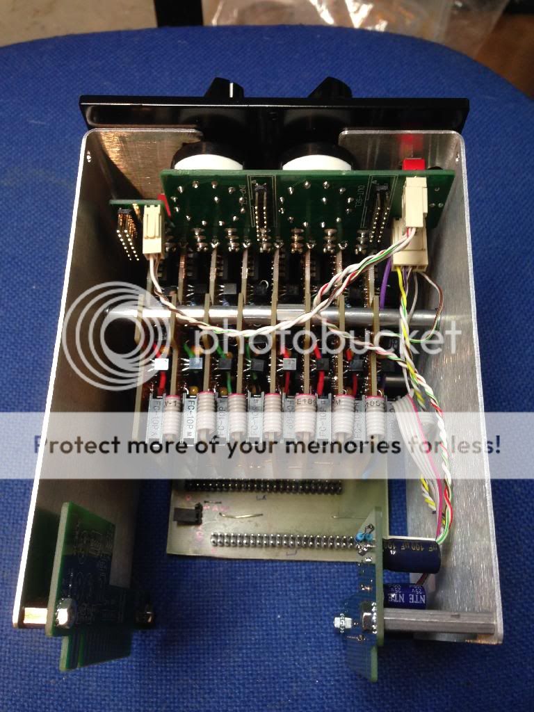
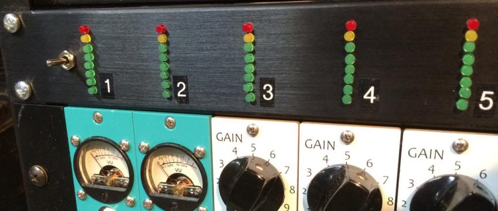
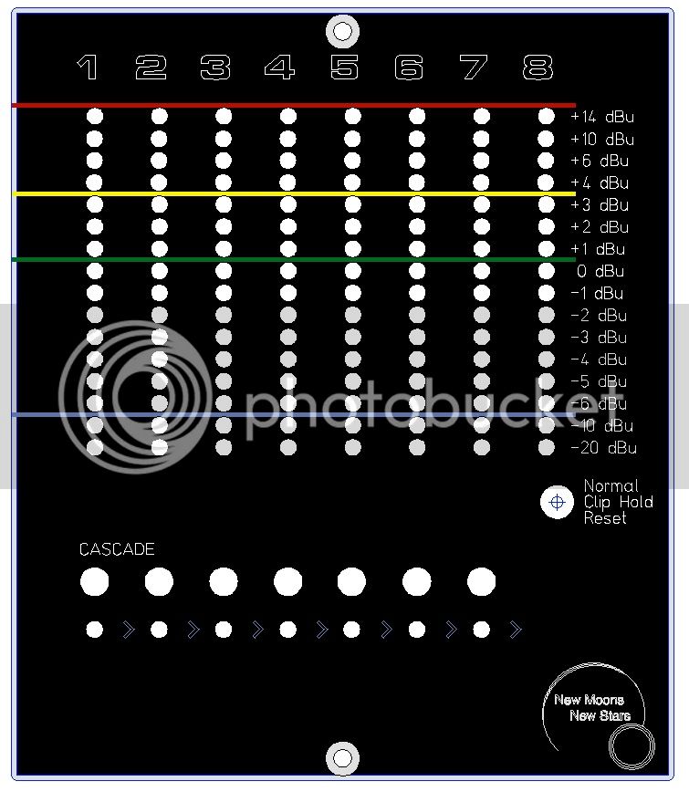
And I am trying to fit the switch board into the front of the this meter module, with a button under each of the left hand 7 meters.  I am trying to mount it with standoffs off the metal case, but I may have to resort to toggle switches (which fit in the same card). 

RM508frontpanel_zpsdd4d032d.jpg


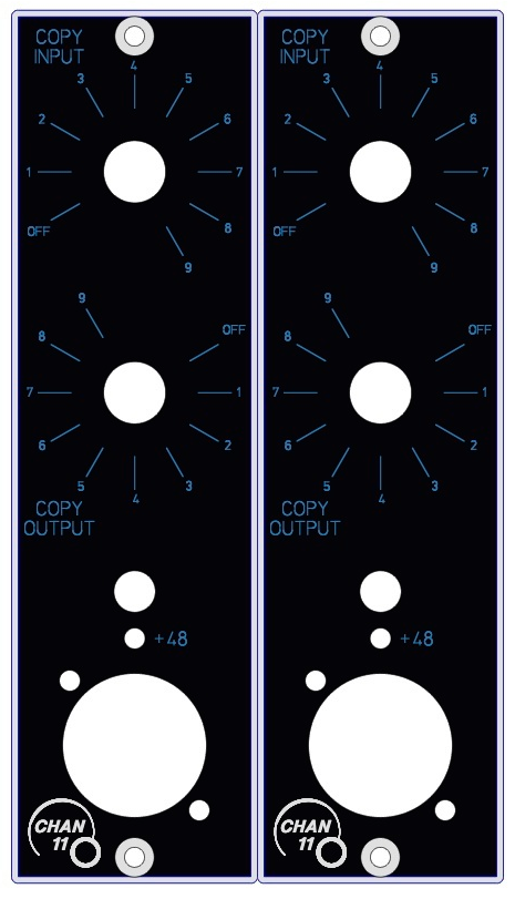
There is a 500 series rack out there where they have switches on the back to do this, but I liked the idea of being able to assemble a preamp and a couple of effects (eg EQ and compressor) on the fly, from the front.
 
bruce0 said:
(By the way.. does anyone know (Volker) if all the versions of the 51x Rack backplane use the same hole spacing?  The holes are never used, so I am worried about them going away).

Yes, they are all the same. The differences in the revisions are:

rev01 - center pin edacs only (prototypes only)
rev02 - added pins for two row card edge connectors
rev03 - fixed one missing stereo link (between module 4 and 5 if I recall correctly)

nothing else changed, and I do not have any plans for further changes.

nice idea!

one suggestion: place the switches between the meters, makes it more clear which modules are connected together (and looks more symmetrical)
 
Thanks Volker... and good idea.

I may be able to cantilever the LED's up between the cards, if I re-layout the card and invert it. 

I agree it will look better and be easier to understand.

bb

Something more like this:
RM508v1_zpsf5670031.jpg

 
I re-engineered the cards and have managed to fit one more functionality into the module.

It now has the ability to
1) Meter with clip hold
2) Cascade the first 8 modules (connect output of 1 to input of 2 etc)
3) Audition signal chains - Module 11 can "copy" any module input and any module output, so you can compare one preamp to another preamp in an "A/B" sort of way live.  This is something I have always wanted to be able to do.  Every Preamp has a sound but the differences are subtle.

Anyway I had to change from pushbuttons to toggles to get it to fit, but it fits with lorlin switches.
Also added 48V power for Channel 11, to reduce pop's while switching from one chain to the next.

It is all done with relays (both the cascading, and the selection of the input and output for channel 11.)

I am a little worried about the 48V being applied to an output while passing through channels, does that present a problem? 

For Example consider the scenario: I have two signal chains to audition
Signal Chain 1: CH1 (preamp) and CH2 (compressor)
Signal Chain 2: CH3 (preamp) and CH4 (compressor)

And I switch from Signal Chain 1 to Signal Chain 2.

I can switch CH11 to connect to CH4 to hear the output of that chain - I don't foresee a problem with that.

But when I switch CH11 from CH1 to CH3 with phantom power on CH11, I will momentarily apply phantom power to the input of channel 2 (the compressor) and the output of channel 1 (the preamp).  Does this present a problem?

Is there a way to apply phantom only to the mic and not to the other end of the signal chain? (If I add another transformer I will add a sound won't I?)

I know if the signal chain modules are transformer isoloated it is a non-issue.  But if they are not trafo input/output what bad effects will I cause, or will it be ok?


Attachments

  • 212.jpg
    212.jpg
    165.4 KB · Views: 21
That's cool...

Moving the mic from one chain to another is a bit clunky though, harder to AB.

Nice things about the way you are doing it is that it makes vertical channel strips.


But I like it!
 
Ok this project has gone a ways further lately.  Still in the lab, but working.

This module controls 3 different PCB's buried in the space between the rack backplane and the back panel of a GDIY51x Rack.

DSC_0076_zps6d908d1a.jpg


The meters obviously meter the 8 open channels (PPM with peak hold, rapid rise time and slow fall time).

The Cascade switches connect the balanced (or unbalanced) output of one module into the input of the next.

DSC_0079_zps78b9d709.jpg


The Channel 11 module lets you use the channel 11 XLR's on the back to audition different inputs and outputs. The knobs sequentially connect the channel 11 input to the first 8 inputs, or the channel 11 output to the first 8 outputs.

DSC_0091_zpse4f4c9a0.jpg


I got the new TASCAM DB25 Cards, and made them with daughter card headers (board to board) so that little daughter cards could ride behind them.  One daughter card is the channel 11 daughter card (20 little relays).  The other is the cascade card (10 little relays).  I needed more than just the 8 or 16 module relays because these relay cards can be controlled by a single slot module (you don't need the whole 3 slot shebang I put together) in which case you can switch or cascade 10 slots.

And of course you can use the TASCAM DB25 connection too. Screws with silver rings are to remind me to use short screws in that hole to avoid driving the screw into the wiring harness!

DSC_0081_zps16cd2348.jpg


The cards fit nicely, I can send pictures if anyone is interested.  The wiring harness is a bit of a chore to put together though, especially in this case where I Cascade, Channel 11 switch, and Meter.

I have some pics of the wiring and the relay PCBs too, which I could post.

Also have some video of it working in the lab.  Just shot with and iphone in one hand and the controls in the other....

Cascade demo

http://s1221.photobucket.com/user/Bruce0/media/Stack%20Meter/IMG_4103_zps34822e19.mp4.html

Comparing Preamps with a single mic using the Channel 11 module

http://s1221.photobucket.com/user/Bruce0/media/Stack%20Meter/IMG_4111_zps9ce78387.mp4.html

Switching both input and output signals to compare a signal processed by different modules (or groups of cascaded modules).

http://s1221.photobucket.com/user/Bruce0/media/Stack%20Meter/IMG_4114_zpsc21b0d58.mp4.html


Here are the little daughter cards.  I had to use smaller relays than the prototype to fit them all.  AGQ2...

IMG_3856_zps2aa72ae1.jpg


They connect to TASCAM DB25 cards, but this version doesn't need to punch the back panel, you can just screw them to the backplane holes (they all line up!).  It is a snug fit.

IMG_3880_zpsa3967f88.jpg


IMG_4065_zpsdfa6bb0a.jpg


The wiring harness is the biggest pain in the neck on this project.  But it all works with some wire ties and patience.  (This may win the award for 10 pounds of ... in a 51x rack! )

IMG_4050_zpsd9396986.jpg


The wiring harness needs to be made sparse by removing redundant grounds (this still leaves 4 ground connections).

IMG_4041_zps1830291e.jpg


And if you look at these XLR connectors, you will see they have all sorts of little "nibs" on them, which make stringing the wire really hard, so you have to snip them all off.

Nibs on both sides and bottom.

IMG_4002_zps80fdab3d.jpg


Some of them are metal nibs, clipped them off (along this row)

IMG_4009_zpsb07e6ff4.jpg


Here they are all cleaned up, you could fly a ribbon cable down these alleys...

IMG_4030_zpsea5b69fd.jpg


IMG_4038_zps605d4134.jpg


IMG_4038_zps605d4134.jpg


Separate control boards for cascade and Channel 11 (though they fit together here).  This is so I can make single module controllers that control 9 or 10 channel cascades, or switch Channel 11 through all the other 10 channels.  Module is built like a brick .... house now as you can see.

IMG_4093_zps1c6c3435.jpg


Without the cross bar it was too springy.  Here you can see the control boards.
D2A198DE-BE42-42AB-A0B8-510D234C9D33_zpss0idzfgo.jpg
 
Hello bruce0,

would you consider providing your project as a kit? This is exactly what we thought of when I first told my colleagues about your tascam/cascade/11slot cards.

GREAT work!

 
I do have the PCB’s, for example, for all the following configurations.  All are possible with or without punching the back panel.

The two least expensive configurations are this one (input only switching for mic pre A/B'ing) and the Cascade module.  Both use less than 10 relays which if you use 12V you can get down to $3.50 or so each. Rest of the parts are lorlin or toggle switches, ribbon cables, connectors and pin headers, hardware and a couple of caps and diodes.

onemoduleChan11Select10inputonly104_zps699f0c19.jpg

 
Cascade 10 slots - uses 1 module space.  Also inexpensive.

Cascade10_zps70a60219.jpg


Compare 10 slots - select from 10 modules - uses 1 module space. optionally front panel XLR. 20 relays.
CHAN11select10FPD_zps0377e4d2.jpg


Cascade and compare 9 slots - select from 9 modules and connect any module output to the next - uses 2 module spaces. 26 relays.

CH11andCascade9FPD_zps760ca791.jpg


You can mount 2 channel select cards, one on channel 10 one on channel 11.  Stereo compare? Probably not useful, and 36 relays!

9Slotnometers_zpsf60dbcae.png
 
Several people have asked if I have the cards for this project.  Here is the project status:

The project consists of several different cards, here is the (ID) description, and status of each:

1) (RECT and METER) Cards requires 8 sets - I have a new version of these on hand, but I have not tested them yet. I used the old version which required patches.  Both types in stock

2) (RM TASC) Cascade relay daughter card - requires 1 - have stock

3) (RM Control) Cascade front panel control card - requires 1 - have stock

4) (CS TASC) Channel 11 relay daughter card - requires 1 - have stock

5) (CS Control) Channel 11 front panel control card - requires 1 - have stock

6) (TASC) Tascam Cards to hold the daughter cards - requires 2 - have stock

7) Meter signal distribution cards - I self etched this, I could order some, or you could hand wire this.

8- Front Panel - I made just one - fpd file is available.

9) (Goldfinger) 51x Card edge with regulator for relays - requires 2 - have stock.


If you are interested in this project, consider doing a small version . I am trying to get a detailed BOM but I have done a rough one and the costs are pretty daunting.

This project uses very small relays (panasonic AGQ2 relays).  They are expensive.  You can use the 12V versions with a voltage regulator, or you can use the 24V ones and the -24V rail (which is what i did).  If anyone had a low cost source of these it would great.

I used 23 relays at $4.08 from Mouser which were $118

I have done a rough calculation, and the module cost me about $573 in parts including face plate.

Anyway if you are considering the project, I recommend smaller cheaper versions using the 1 module faceplates posted earlier.
Given the cost of the project I don't think there will be enough interest to make it worthwhile doing kits. I can provide the boards if anyone wants to damn the torpedo's (like I did!).


Delayed:

I may need to make a custom backplane for the 51x. 

This might be the only way to go as the newest backplanes over at ClassicAPI don't seem to support the 50 pin headers needed.  This may be for the best anyway, because with a custom backplane I could support plain old switches for Cascade routing, and there would be lots of room for big fat cheap relays.  Furthermore I could just stick the TASCAM connector to the backplane and even have the option to avoid the XLR's all together. And the snaking and routing of ribbon cable could be avoided.

Anyway:  This mixer project is on hold till I find out what is happening.  I have sent a note to silent:arts to see if he will still be making the backplanes with pin headers or whether they are all going new style.

I am prototyping a Mixer Support Daughtercard (MX-TASC).

It provides relay switching of 10 balanced pairs to a 20-conductor ribbon, which is laced around the backplane to the circuit in the module bay.  There is a DPDT relay on each output controlled using the same card used to control the cascade module (CS-Control).

I plan on having the "off" contacts of the relay connect the cable to a resistor to ground to provide the ability to have constant impedance mix bus (for passive summing) but if anyone has a better idea of where to switch the other side I am open to it.  Maybe there should be an option for a second full ribbon to the module bay.

Of course this can be done with two 50 pin ribbons, but I know from experience they are very difficult to route in the 51X box.

I have to figure out the mixer module and front panel but I think I will use a virtual earth mixer, run outputs through Slot 10 and 11.  Allow the bus to be expanded through connection on Slot 9.  Maybe use the inputs for slot 10 and 11 as monitor outputs?  Headphone amp?
 
Another approach for metering. 
11 meters, in 1U rack, each meter above a module.
Uses no module slots, easy to see which meter goes with which module.

VU8-11_zpsef24e278.jpg


Connect all 11 via 2 short TASCAM cables (male-male)
TASCAM through connection.

VU8-12_zps567537ab.jpg


Clip hold mode, PPM metering with range of 0dBFS to -42dBFS in 6dB increments.  0dBFS adjustable on a per channel basis.

VU8-1_zpsd067fae8.jpg


(Side note on Middle Atlantic 1U case. It fits, but I will never again use a Middle Atlantic case.  It is strong but really strange construction, and significantly reduced vertical space, hard to mount front panels, screws only good for a few insertion/removals before they destroy the threads, a truly bad design.)
 

Latest posts

Back
Top