outrecording
Well-known member
The links are helpful. Thank you.
I went with the Fab filter FAB1248: http://www.fabmodules.com/shop/index.php?route=product/product&product_id=50
From what I can tell, it seems it won't be a noisemaker? At any rate, it shouldn't be difficult to add filtering after the fact.
I went with the Fab filter FAB1248: http://www.fabmodules.com/shop/index.php?route=product/product&product_id=50
From what I can tell, it seems it won't be a noisemaker? At any rate, it shouldn't be difficult to add filtering after the fact.
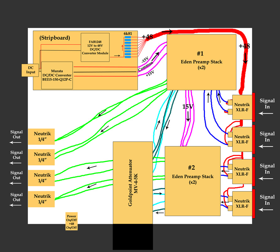
bruce0 said:I don't know how the Expat guys support phantom switching etc, is it on the board? Do they have a suggested schematic?
There is a GREAT set of articles on the topic from thatcorp start with DN-140 (http://www.thatcorp.com/datashts/AES7909_48V_Phantom_Menace_Returns.pdf http://www.thatcorp.com/datashts/dn140.pdf ) if the eden folks don't have a schematic for you. DN-140 deals with lots of phantom switching approaches, but not really filtering. What supply are you using, let us know and we can take a look at the spec and make a recommendation but I suspect you can use something like the schematic mentioned below for filtering.
Any complete schematic of a phantom supply will have filtering caps on it (in combination with the supply resistors the stabilze the supply) but they don't necessarily have to be on each line (since you are tight on space, and connecting this to a "known" type of mic. ) or mounted directly to the XLR. Also a filter arrangement would have a resistor before the cap, as you will see in most phantom supplies.
As an example look at page one of this schematic http://www.soundskulptor.com/pdf/mp66-schematic.pdf The phantom power has a RC network to filter it (R7, C3) and another (r6, C1, and C2) and C1/C2 caps also act as a reservoir like the one you show in the picture.
I use the soundskulptor schematic as an example because this particular one has a switched mode supply in it (it is a tube preamp and has one for 250V SMPS supply is shown on the schematic. Incidentally you can see an LC and and RC filter are in use on the 250V supply before it hits the vacuum tube. This type of LC/RC combination is typical (for low noise rails) and I am sure will be the case in whatever SMPS (switched mode power supply) you choose)