great british spring reverb tank replacement

GroupDIY Audio Forum

Help Support GroupDIY Audio Forum:

This site may earn a commission from merchant affiliate links, including eBay, Amazon, and others.

salomonander

Well-known member
Joined
Aug 28, 2011
Messages
913
hey
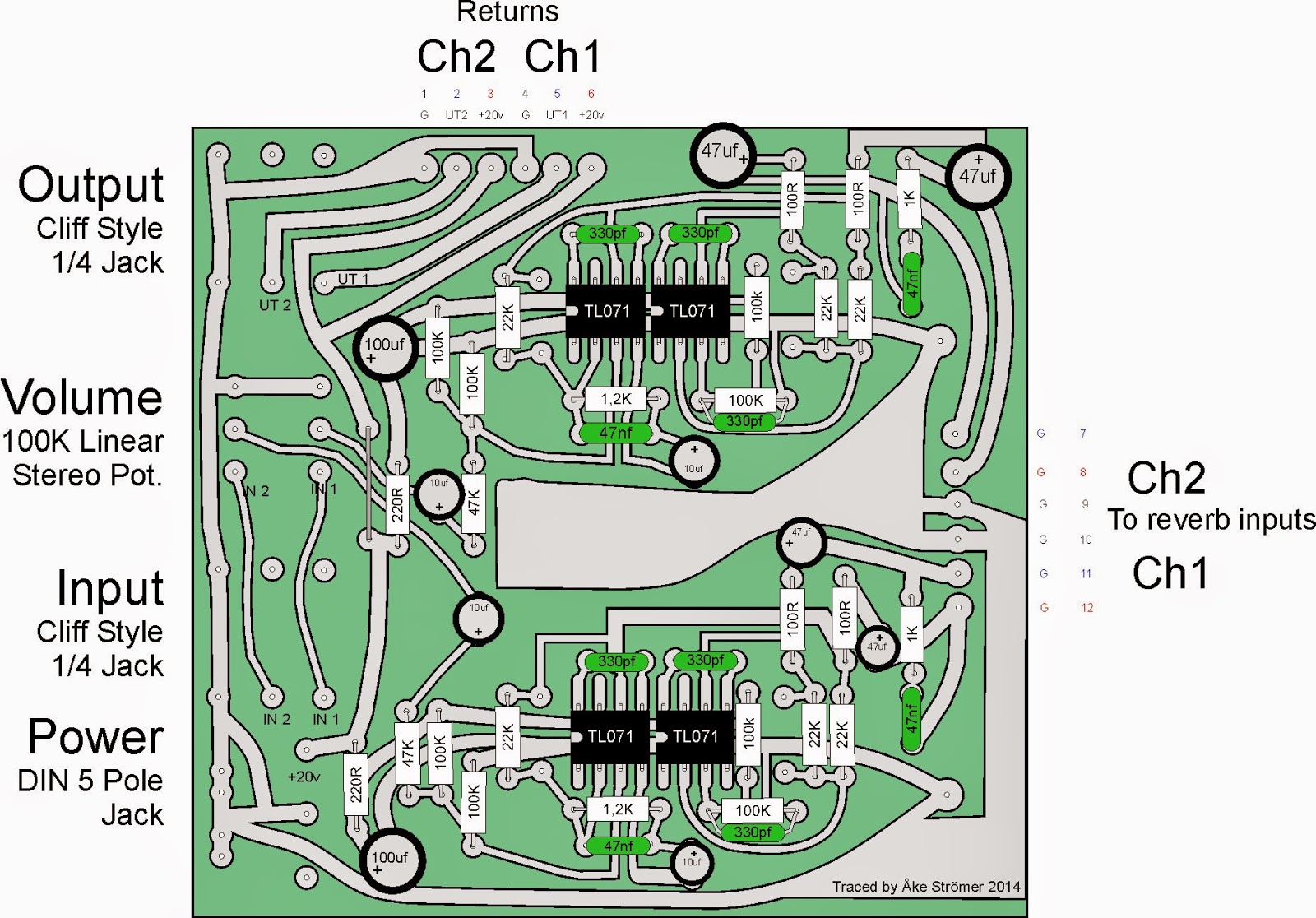
one of the spring tanks in my great british spring reverb has a broken coil and needs replacement (accutronics). problem is that there is no part number on the tank. im pretty shure that its a type 9 but i have no clue which exact version.
does anyone know perhaps? i also have the same tank - working (other channel). in case it is possible to measure this somehow. thanks a lot
 
1.33 works for loudspeakers, but I think Hammond Springs have a higher ratio.

There IS a table on-line somewhere with nominal (audio) impedance, DC (ohm-meter) reading, and type-numbers.

Also the coil form color implies the nominal impedance.
 
PRR said:
1.33 works for loudspeakers, but I think Hammond Springs have a higher ratio.

There IS a table on-line somewhere with nominal (audio) impedance, DC (ohm-meter) reading, and type-numbers.

Also the coil form color implies the nominal impedance.

my coils are yellow.... well ill just call up accutronics tomorrow. looooong distance call i guess :)
does anyone know if it is possiblee to swap the coil only - not the entire tank?
 
Who knows the exact type number of the reverb tanks in the Great British Spring?
I measured the DC resistance in mine, and found 33 ohms for the drive coil and 722 ohms for the pickup coil.
And what type did they use? (Short/medium/long?)
It seems there once was a type number stamped on the enclosure, but they made it invisible with a black waterproof felt tip pen...
 
By the way (for what it's worth): I found that the ripple rejection of the supplied power supply can be much improved by replacing the 100 uF capacitor across the supply lines of the first TL071 OpAmp in the recovery amp (inside the reverb tank, after the 22 ohms resistor) by a 1000 uF/25V one. The improvement in hum of the recovered signal is significant.

Also I had a problem that the high frequencies in the input signal (only the right channel) leaked through in the output. (Of the left channel)
The reason for this is that the reverb tanks are stacked above each other in the PVC tube.
This means that the drive coil of reverb tank one, (magnetically) induces a voltage in the receive coil of tank two.
To solve this, I placed the reverb tanks with the open sides to each other. (so 'parallel' to each other.)
This solved the problem completely!
The only thing is that I have to find a wider tube now... (125 mm will fit.)
 
Hi!

The tanks in my great british spring are 9dc1d1e.

One is missing the springs so I just requested a quote for how much a replacement tank would be.
 
1 tank ended up being $68 with shipping to New York. $105 for two.

I traced one of the GBS's we have here at the studio. And here's what I came up with. I'm gonna try and draw a proper schematic for it too. But that might take a while.

Main.jpg


Ch1.jpg


Ch2.jpg
 
Hi!

The tanks in my great british spring are 9dc1d1e.

One is missing the springs so I just requested a quote for how much a replacement tank would be.
Great work on the tracing. I have a MK3 which has a the NE5534 and a slightly different layout. My DC resistance is also 35ohms I/p and 760 o/p.

The recovery amp is 2 x TL071
 
Last edited:
Back
Top