Telefunken V672/2 output level control

GroupDIY Audio Forum

Help Support GroupDIY Audio Forum:

This site may earn a commission from merchant affiliate links, including eBay, Amazon, and others.

bram9206

Well-known member
Joined
Aug 1, 2011
Messages
98
I have here two Telefunken V672/2 preamps racked up with 20dB pad, phase reverse and a switchable gain control. All is well and I'm really happy with the results, but now that I'm making a real nice 1U rack for them (they are now in an ugly eurorack), I also want to add an output level control so that I can play with the input level. I got the idea from working with the Chandler TG2 preamps...

I already did some research on the web, but can't find a thread about the output level control. All I find is info on the gain stage...

So I guess what I need for this output level control is a simple pot meter? Logaritmic? What value? Anyone knows how to hook it up?

Thanks a lot for any help!
 
Nobody who can help me out with this?

Any help, ideas and thoughts are most welcome. Thanks!
 
Hello,
If you use a lets say a dual 500 ohm Poti as a shunt you problably alter your balanced Signal, because potis have a not good linearity generally and under each other  that destroys Your Protection because  positive and negative  Signals are not equal anymore . The Outputimpedance of this Amp is something like 50 Ohm so you could calculate a 500 ohm  PAD for this Application. I don t have a Link to calculate it handy in Monent but if you search for Pad calculation you will find Information. When you work with Pads it s important that the Voltagedivider fits the given Impedance, both from Load and the inputimpedance from the following Unit. When it is missmatched you may create a frequencyrelated voltagedivider .When You calculate for a 500 ohm Pad you may need Resistors out of the 96 pattern, so 2 resistors in Series can be used to get the  Value. After the Pad You have a Sourceimpedance of 500ohm so the inputimpedance of the following Unit should be min 5 k Ohm to reach a solid Voltagecoupling.Keep this in Mind that you change a given Impedance with a Pad.
Maybee you can use a 100 ohm poti as a  voltagedivider before the outputtranny,after the
outputcouplingcondenser] (to avoid a change in the dc Feedbackloop of the Amp)  If you use the wrong pad,poti you may missmatch the Outputtranny. I would go for a 6 Step 2 Level Switch like a Lorin  after the Outputranny , or if you want more Steps there are nice but expensive Multistep/Level Switches up to 48 Steps with 8 Decks in the Offer. If You calculatate the Steps clever , 6 Steps are very usefull if you want some Drive from the Amp with no overloadproblems of Your ADC. If you want more Steps the practical construction of the Voltagedivider gets complicate because the  Value and difference of the used Resistors gets very small and 3 Resistors in Series may be nessesary.Try to get the Resistors in both Lines as close as possible to keep the balanced Signal equal. Good Idea, by the Way.
Thanks, Greetings    Lothar
 
Hi,

i've racked 4 of them. Go for JLM GoBetween plus Variable Pad Kit - and you're happy!!  :D

Rock-ON!
 
I checked some of the JLM stuff, but I already have everything I need (pad, phase and stepped gain). The only thing I need, and which they don't sell, is an output control. Today I opened up a TG2 and I see they are driving the output stage (like a fader). The output pot is wired before the output transformer, but all the rest is kind of difficult to see when you don't have schematics... and the sum option doesn't make it easier...

So I probably should wire some pot meter before the output transformer, but what pot and how...? Any thoughts?
 
Hello,
I would go with a 500 ohm Pad after the Outputtransformer. If you use a Poti inside,you really have to know what you are doing if you don t want to change the whole Amp for the Bad .You could try a 100 ohm linear poti in series after the Outputcouplecondenser to create a Voltagedivider in conjunktion with the primary of the Transformer, this could give you 12dB of Range. But if you turn clockwise you have less Level.Lift the side of the condenser going to the Tranny,connect the input of the poti and the wiper back to the place where the condenser was before.But I can be wrong with this. After the pp outputstage you are already very low in Impedance.With a poti in Series  the Outputtransistors "see" this poti as a Load, the Outputranny "see" the poti as Source instead of the Outputtransistors. I dont know if it s a good idea.The Chandler has a higher impedance primary winding than the Telefunken,so you can t take the same value Poti.
Greetings
Lothar
 
Thanks Lothar, but you're probably right, if one wants to fumble around before the output transformer, one has to know what he's doing. And I don't have enough knowledge to do so... unless you could give me very detailed instructions, because I do know my way around a little bit in electronics (see my Pultec http://groupdiy.com/index.php?topic=54468.0)

Another thing I heard is to put a dual lineair 10K pot between the output transformer and the output XLR. Here's the schematic:
output%20control.jpeg


Anyone knows if this is a good idea?

Thanks!
 
Hello Bram,
You are very welcome.i am happy if i can help you a little bit,a rare Situation here for me because i respekt this place alot and don t want to give wrong Information. Maybee someone who is more informed than me could correct my wrong thoughts,that would be nice... its also interesting for me.
Your Solution may work,but. 
1) These Outputtrannys don t like to work into a high impedance Load.They like something like 2 k ohm or less , if you connect a 10k Poti like done in your configuration your Outputtranny don t like it too much.and
you also end up with a variable Source impedance related to the given Position of the Poti for the next Unit.
Let s say you like to power up a 1176 as the next unit or another vintage gear with low input impedance input like a  Neumann,Filtec,Tab,Siemens etc EQ, you may get a very bad sound with this Konfiguration, harsch mid s ,less Bass, distorted high Freq..Impedancemissmatch.(frequencyrelated and general Levelloss) i can talk from own experience,i pluged some of my V 76 stuff in the not best way in the Past I concected them directly in my Da 88 and my Ampex R2R ,they both have the modern 20 k ohm inputimpedance .Now they sound much better because I  terminated the Output with 1,5-2,5 kohm.(just put a Resistor in this Range between pin 2 and pin 3 in the xlr,)but only if you plug in in a unit with at  least 10 k Ohm Imputimpedance,  if you go to prof. vontage gear , than without this Resistor)
The next is the lost balance  between the Lines, caused by unlinear Potis.Expekt plus minus 4-7 dB or more. Thel audio offers laser trimmed precission Potis, they are nice but dost something like 100 each. If a dualpoti is the wish i woud go for 1k or 1,8 k Linear, than you can connect most of Your Audiogear without thinking all the time when you change something in the Patch. i really think that a standart Poti in a balanced Line is a bad thing because you destroy your balanced signal and if Transformers involved i think You loose a important part of the advantages of Transformercoupling when  a resistor is in between. The Outputwinding "see" the resistor Load (the Poti, or a Resistor ) the Inputwinding of the follwing Transformer also "see" a resistor instead of the coil .......,i don t know...
Noise may also come to mind with your 10k ohm solution.
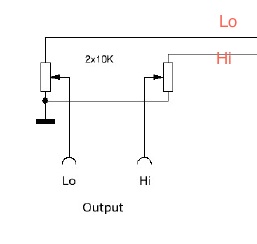
You can build a few different Patchcords with different damphings first. Just tie a 500 ohm Resistor between pin 2/3 and a 500 Ohm in each (posive,negative Audio )line.that shout be a -6dB Pad.The Resistor between the Audiolines represents the Load for the Output 
the Resistors in the Lines represent the Load for the next input.
I have a nice artikel about how to calculate the correct Pad. http://www.uneeda-audio.com/pads/    Hope this helps. Its very good explained how  to build a matching Pad.
An other possibility could be to put a 2k Poti between the positive and negative Audio. The Input from the poti in the positve, the wiper to the negative, leave the endpart from the poti alone. 0 ohm means short,no Signal ,if You increase it should be variable Output ,you can try ..i don t know if it s good and works only in units with a good balanced Signal.,  But this impact  change Your Impedance as well.    i saw this Way of Dampening the Output in a Eastgerman Isolationamp i really like to use.after moding.
I would stay away from Potis.  This Amp is a fantastic peace of Gear, so i wouldn t mess around with that perfektly balanced  Output Signal,only with a matched Pad you can be shure to have the full potential left.
Greetings from Berlin
Lothar
 
Hello,
Another Idea came to mind. You also could get you a aktive Fader, Telefunken, Lawo Ant.etc They can be found relativly cheap at e.  y Germany .Together with a Termination Resistor and or a variable coarse PAd before the aktive Fader You have a lot of Posibilitys to drive your DAW, or if You want to connect something else you could take the Fader and the Rest out of the Signal. But than you are on the save Side in term of impedance and fine Leveling, you already have a hopefully oversized 24 Volt Powersupply in Your Rack, or you could build one by Yourself since Pcp s are avaiible in the white Market. It s easy to build and a good Learning, the Highvoltage Part is dangerous ,but maybee you can use the already existing Terminals and plug a new Transformer and your homemade Powersupply to them.to power the aktive Fader if you don t have enough current in your existing Powersupply.
These Amp s where designed to drive passive 600 balanced Faders from Maihak w66 /86 or siemens and the famous eckmillerPassiv Fader who has hundreds of taps out of the Transformer ,so for every Level a different winding ! They People these Days had to do a ultra precission Job to keep the whole Radiostations working. So it would be technical possible do use also a  600 ohm vintage balanced Fader  because this Amp can even drive a 300 ohm Load at +21 dB. in spec s .
On the other hand it can be that it is better sounding if these kinds of Amps are terminated  with 2 to 2,5 kohm when pluged into modern Stuff.like DAW s.
The other unwanted is that even with these hightech precion Faders You have a Faderpositionrelated Outputimpedance with these passiv stuff.This may or may not have an impact ,depent s on what You plug it to.
Sorry, all this may confuse but i think it s quite important  to mind this Impedancething, everybody knows about Level. dBu et stuff but when it comes to Impedance "Leveling" ...........................(me defenetly including).  it s a complex Book. i saw pro s and amateurisch Producer,Mixer who pluged 60 s Fender Tele s directly in a Mic Amp or Line Amp .
Greetings
Lothar


I did some resarch and found out that the manual of the V672/1 I have (can be found at Kubrath) matches a 100% with my V672/2 preamps. I don't understand why the manual says V672/1, but the schematic matches my V672/2 a 100%.

This said, I have here a copy of the output stage. Anyone any idea where I can put that output volume control pot? Do you think I can just put it at the input of the output stage? And what pot value?

v672%20output%20stage.png


Hello,
If you put a Poti in this position,You may change the whole topology for the bad,the pull push balance  is defenetly gone ,the outputstage could loose it s operation Point as well. If you want to do it like this nevertheless,You need to find a dc free position,like after the outputcondenser,whitch is not seen in your part of the Schematic you posted.if you put a poti as a shunt after the condenser,the resistor going to ground lies in parallel to the primary winding of your Outputtransformer.That lowers the load your outputstage must drive,  this may work but i don t know ....if you put a poti in series ,something like 100  ohm linear , to create a voltagedivider together with the primary winding of your Trafo,the Range of adjustment is not very large, i guess,  As I said before i am not a superexpert,but i know enough to see that it s not as easy as you maybee think and would have been done by others before,  that s why it would be nice if someone with more skills could join this discussion and could say something  if my thoughts are right or if it s just paranoia.  Please post the rest of the Outputstage ,including the outputcap and Tranny.
Why don t you want to use a calculated Pad after the Outputtransformer? In the Link i gave You, everything is explained very good .
Greetings
Lothar.
 
Hello,
Thank s for posting the schematic. The Outputstage is connected to the whole Feedback Loop of the Amp. I think You made the Gain adjustible this Way. Problably  You use a Poti  whitch is feed from the same Output via another  condenser and a second Outputtranny, and comes back in the secondarys of the Inputtransformer. As a adjustible Feedbackloop to adjust Gain. I would absolutly! Stay away from changing anything in this Design. If you put a Poti  as a voltagedivider, or a as seriesresistor in the Line you change the whole thing , i think. The whole Feedbackloop may be effekted  because both Transformer s are matched to each other, the whole design around , the secondaries of the Inputtranny,and the Preampstage,too!
You can try with the Poti but than i would connect  it to proper Testequipment  (Frequencygenerator with a 200 ohm Output. TerminationResistor before the Scope and maybee a Nf Milivoltmeter or a pc based Setup.) Than i would watch distortion and Frequenz at + 18'dB  working into 300 Ohm. Than you can judge what s going on if you move the Poti.
A good matched variable Pad is the way i would go.but this is only my oppinion. Even this Pad can cause a  impedancemissmatch if wrong calculated .
Greetings
Lothar
 
For a while I was quite bussy, but now I have the time again to get back to my Telefunkens. In the meantime I did some googling for t-pad attenuators and I came upon the t-pad attenuator Hairball Audio is using for their 1176 clones.

http://www.hairballaudio.com/shop/product_info.php?cPath=27&products_id=65

Would that be something? I feel like this could be THE solution I've been looking for...

Anyone any thought?
 
Specs:
Series 51 1/2" Modular Potentiometer

Module 1 - Conductive Plastic Element
Resistance - 500 ohms
Linear taper +/- 10%

Module 2 - Conductive Plastic Element
Resistance - 1K ohms
CW Modified Log taper +/- 10%

Module 3 - Conductive Plastic Element
Resistance Value- 500 ohms
Linear taper +/- 10%


Hello,
I also like the Hairball Stuff ,but as i said before even the good Potentiometer have a plus/minus 10% Range. This is a possible 20% total Difference. You could buy one , install it ,find the wanted damping,than messure out each Poti ( 2 in Series and 1 parallel to the Outputtranny) find the next E96 Value or series 2 Resistors and install them to a 3 Deck Rotary Switch in the same manner like the Poti. A Lorin or Alpha 3 Deck/ 4 Position Switch is a cheap Solution, if 4 Positions  like -3/6/9/12 dB Steps are enough.If You use a Switch, use a " Make before Break" , that prevents popping when switching. I think using the 600 T Pad will work also, but at a cost of a not so good balanced Signal and a lost Stereobalance if You use 2 Amps for Stereoapplication, if you put the Poti visually in the same Position. But this can be solved if You calibrate the Outputlevels first and mark each equal Position at the Frontplate.
I don t want to confuse You, I just try to be technical correct as much as possible.
So yes ,the Hairball T Pad  is a possible Solution but not "The" Solution, this would be a high Quality Switch with matched 0,1 % Resistors. 1% is also OK.
Greetings
Lothar
 
Hello all,

just to let you know I finally had the chance to test the Bourns T-pad attenuator from Hairball Audio and it works just great to attenuate the output level of my Telefunken V672/2 preamps. I did several tests to check if I have any loss in the quality of my output signal, but it sounds just great. And with the Telefunken's 1,5dB finetune gain control I can find the best sweetspot at the input and attenuate it to a normal level at the output!
Also, the next piece of gear in the chain (which in my case is an EQ) still "sees" the 600 ohms at the input.

End of the story!
Thanks for all the info, especially Lothar!

 
Hello Bram, Beautifull Work!!!
Just remember that your Z out is now something like 500 Ohm, varies with the position of the Outputpoti.. If You plug a Unit with a low Inputimpedance like 600 Ohm, you leave the voltagecoupling and get a currentcoupling. It s ok as long as You are happy with the Sound.You may loose a few dB s of Level ,SNR and Headroom .
Happy Recording!!
Greetings
Lothar
 

Latest posts

Back
Top