Help needed for finalizing schematic

GroupDIY Audio Forum

Help Support GroupDIY Audio Forum:

This site may earn a commission from merchant affiliate links, including eBay, Amazon, and others.

Gachet

Well-known member
Joined
Feb 15, 2006
Messages
144
Location
Bordeaux France
Hi everyone

I want to build a 2 input mixer.
The particularity is that One input is line level and the Second input is guitar pedal level ("Disto Input")

The purpose is to parralel line level input signal with distorted signal from guitar pedal.

I need some help to find correct cap and resistor values. I've put some values already, but I'm unsure about it.

Do I need extra resistor and cap in parallel with ground on output stages?

I am not concerned phase wise as Ican flip the phase of my distorted signal with reamp box transformer based I use for feeding the distortion.

The output will feed a DRV134.

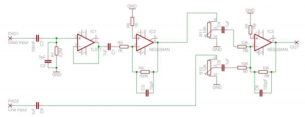
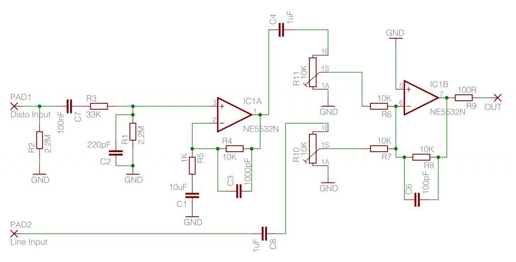
Here is my schematic.
Schema.jpg


Any comment or help will be much appreciated as I'm not very skilled in electronic.

Thanks
 
IC1 is a unity gain buffer. There is no need for R2 and C2. You can connect pin 6 directly to pin 2.
The gain of IC2 is 100 x, this means that any DC offset at the output of IC1 will also be amplified.
I would prefer a capacitor between the output of IC1 and the input of IC2.
Are you sure you need 40 dB amplification in this stage?!
C8 (100 nF) is a bit on the low side for a 10 K. pot. This will give a low cut under ca. 150 Hz.
I would prefer 1 uF or more in this position.
 
Why IC2 in inverting mode ? There is a possible phase cancelling issue depending on the source material "parralel line level input signal with distorted signal from guitar pedal", it presents also an heavy load for TL071
 
RuudNL said:
Input impedance of IC2 is only 1 K, so I would use a value of 10 uF (22 uF) or more for C1.
(-3 dB @ 15 Hz or 7 Hz.)

Ok good.
Maybe I should raise R3 Alittle.


keefaz said:
There is a possible phase cancelling issue depending on the source material

I have a switch to flip phase on my re amp transformer, because some pedals can cause phase shift.


keefaz said:
it presents also an heavy load for TL071
I'm not aware of that.What does that mean?

Thanks to both of you
 
> gain of 100 is what I've found

Something wrong there. A guitar distortion box typically puts out 0.25V, 0.5V, or more. Times 40dB is 25V-50V.... and we can only get 10V out of that amplifier (assuming +/-15V rails).

Even tube guitar amps (with much higher overload levels) rarely give over 34dB gain before some kind of volume control.

Put a trimmer on that amp.

The buffer+inverter is pointless. I don't think the phase inversion is an issue, but it's just complication. Non-inverting will give your gain of 100 with a high input impedance. (The drawback is that it won't give a gain of less than 1, but you are nowhere near that.)

You do NOT want hypersonic frequency response, either in compact high-gain systems, or for guitar work (especially e-guitar, especially distorted). I've set your gain-stage for 15KHz upper limit. I suspect C3 could be 200, 300, even 500pFd and give good guitar.

Always "bleed" the "outside" (jack) end of input coupling caps. Some guitar pedals leak a little DC. When you switch/bypass them, the change of charge "POPS".

Always put some resistance between the Big Bad World and your chips.

Guitar-level inputs are prone to catch radio stations. 34K plus tube capacitance has worked well for half a century. Since your chip has less stray capacitance than a tube, throw a couple hundred pFd there.

The Gain=100 stage will have large DC offset (part-Volt). You need to block this before the mix pot. Since the pot is grounded, you do not need to block again before the mix resistors.

'5534 should have a compensation cap. With just two opamps you can use '5532 which does not need compensation and saves a lot of solder joints.

'5534/'5532 needs good 10+uFd power pin bypass caps *AT* the power pins.
 

Attachments

  • Gachet.gif
    Gachet.gif
    18.5 KB · Views: 35
PPR You are so cool  : )

PRR said:
> gain of 100 is what I've found

Something wrong there. A guitar distortion box typically puts out 0.25V, 0.5V, or more. Times 40dB is 25V-50V.... and we can only get 10V out of that amplifier (assuming +/-15V rails).

There is definitely something wrong, I measured 0,016V at the secondary of the  transformer that  I used to adapt the line signal to the input of my big muff. I've calibrated it with the pedal in bypass.
I assume I've attenuated too much the signal even if I could get nice distortion from that. The output pot of the distortion was low too.

I will review my shorting resistor on the secondary to match the 0,25 0,5 V you're talking about.

Anyway I have the impression you did all the work here.
Thank you


Concerning my transformer to "reamp", I have now 0,25V at secondary for 1,66V at primary.
It seems ok for me.

I need a gain of 6,64 to rich back the 1,66v at input (dry signal)
So I think I can go for a fixed gain of 10 and avoid the frequency response to change with the gain.
I still have the mix pot to lower the signal and match the dry signal level.

So a 10K resistor in place of the gain pot, paralleled with C3 1000pF.

 
hi

parrallelmixer4PRR.jpg


I have made the circuit corrected by prr on a breadboard and I have to say it works great, much better than my initial plan.

I ran some triangle and square waves thru it and I noticed at various frequency that the triangle got rounded and the square duty cycle got very low.
I tracked the signal from input to output an find out that c4 the 1uF before the 10k pot was responsible for it.
It goes away when I increase the value. I had some 10uF bipolar electrolytics that seem to do the job well.

Is it relevant to increase that value?
Is there a drawback doing this?

Thanks
 
Gachet said:
JohnRoberts said:
The worst case 5k x 1uf is -3dB at 30 Hz, pushing that C to 10uf pushes HPF pole to 3 Hz.

Is that too low?

For what? In general I try to avoid using electrolytic caps to form audio frequency filters, they do not make good filter caps. Set the electrolytic poles way low, and then make one higher pole using a film cap to dominate the path response.

I do not feel like redesigning your circuit (then it would be my circuit). You have several poles there, it would be good to review them all in the context of your desired path response.

JR

_-3dB freq= 1/ ( 2 X pi X R X C ).
 
JohnRoberts said:
Set the electrolytic poles way low, and then make one higher pole using a film cap to dominate the path response.

I assume, you mean something like raising the frequency of the first pole in the signal path, for example from 100n to 4,7n and then have 15Hz instead of 0,7Hz HPF pole. And then leave my 10uF(maybe higher) in place of the 1uF.

Anyway, thank you JohnRoberts for your help.


> triangle and square waves thru it and I noticed at various frequency that the triangle got rounded and the square duty cycle got very low.

WHAT "various frequencies"??

Sharp-cornered waves will ALWAYS go rounded at some high frequency. No amplifier has gain flat to arbitrarily high frequencies. We test with squares (especially) because a mid-frequency square will *instantly* show if there is some serious problem.

A 700Hz square that comes out very nearly square means the amp is pretty flat 70Hz-7KHz and tolerably flat an octave or two more (20Hz-20KHz). Top-tilt is bass loss, round corners is treble droop. It can be quite visible on a sharp 'scope without being audibly band-limited.

However we do not need 100KHz or 1Hz squares to come out "perfect".

Not sure what your "duty cycle" is. However a Square is not good about showing "clipping". If you OVER-drive many good opamps with a 50:50 wave, they get off-balance and may show a 30:70 wave. But that is well into clipping, which is more offensive than duty-cycle change.

If you are doing clasical orchestra with mikes that cost as much as a car, you *may* want -1dB 10Hz-50KHz all the way from mike-jack to recorder input. "MAY", because sub-sonics and super-sonics can garble the signal. Some very serious classical music systems for broadcast had sharp filters at both ends of the "useful" band, even 50Hz-15KHz.

But this is a Re-Amp? Bah. While your original 100nFd+10K input would have been bass-less (which can be good for guitar), 1uFd+5k (5K because at full-up you have both the 10K pot and the 10K mix resistor), 32Hz, is plenty-enough to get the guitar into the recorder, and probably way better than the amp you are re-amping in. Lower tones are studio blower rumble which detracts from the music (even though unheard, it suggests pitch instability and unsettles the more musical listeners). Then in final mix-down you will twiddle the 82Hz-160Hz band up or down to get the desired "phatt" or "scream" in the sound.
 
Thank you PRR for clearing things up, always a pleasure.

I redid the test with 250Hz square wave (no clipping), trying different caps, and here are the results:

Reference signal:
referencesignal.jpg


1uF 250V WIMA:
WIMA1uF.jpg


1uF 63V standard poly:
Polystandard.jpg


Bipolar electro 10uF:
Bipolarelectro10uF.jpg
 
PRR said:
But this is a Re-Amp? Bah. 

It's a box to add parallel distortion (guitar pedal) on a vocal mike, trombone or whatever coming from balanced line source.
It's for "live" apllication.
The schematic is the return of wet and dry signal.

And I'm just curious...
I'm really enjoying the research work and thanks to you  I learned a few things in the process.
 
The difference between two "1uFd" caps is very suspicious.

I would use a Sine wave source to get a plain old frequency response. _IF_ you are really wired as seen in the drawing (never trust your own work), it should be -3dB at 32Hz.
 
PRR said:
The difference between two "1uFd" caps is very suspicious.

Yes it was u1(100nF) and not1uF  :-[

PRR said:
I would use a Sine wave source to get a plain old frequency response. _IF_ you are really wired as seen in the drawing (never trust your own work), it should be -3dB at 32Hz.

I might down a little c3 to have less hi frequencie roll off, but I think it's the breadboard that flaws the value.
So I'll check it when doing the real thing on veroboard.
Capturedrsquoe3010cran2014-04-21a3000160811.png


I've also added a zobel network at primary winding of the transformer to get rid of a little Hi boost
It took me five minutes to find the right values by experimentation.
I also found some info here:
http://www.muzique.com/lab/patent1.htm

I think I'm ready to go go now 8)
And again thank you PRR
 

Latest posts

Back
Top