You are using an out of date browser. It may not display this or other websites correctly.
You should upgrade or use an alternative browser.
You should upgrade or use an alternative browser.
Ampex AM-10 Mic Preamp & MicPre Front End (Added Circuit & PCB Docs)
- Thread starter ForthMonkey
- Start date


Help Support GroupDIY Audio Forum:
This site may earn a commission from merchant affiliate
links, including eBay, Amazon, and others.
ForthMonkey
Well-known member
Added PCB docs. I need some info...
ForthMonkey
Well-known member
I have some questions.
Why should i use tantalum caps instead of C1?
What is resistor wattage?
Can i use BC239 instead of 2N5088? It has reversed footprint.So easy to fit PCB.
Thanks.
Why should i use tantalum caps instead of C1?
What is resistor wattage?
Can i use BC239 instead of 2N5088? It has reversed footprint.So easy to fit PCB.
Thanks.
> What is resistor wattage?
Get a rough idea of total power consumption.
WORST-CASE, assume that power comes in via R1 3,900 Ohms, and all the rest of the circuit is a DEAD-Short. That says the power CAN'T be more than 24V/3,900 Amperes, 6 mA, at 24 Volts, is 0.147 Watts.
Obviously the "rest of the circuit" is NOT a dead-short. So there is less than 24V across R1. Typically an input filter like this drops 10%-20% of the incoming voltage. 2.4V to 4.8V. To make it easier, compute 3.9V/3,900 Ohms. 1mA. "The rest of the circuit" takes about 1mA at 20V, or 0.020 Watts.
And this is probably split among several paths (R6 and R16). So more like 0.010 Watts in the hottest resistor.
There is some loose figuring here. Do we have to get the sharper pencil?
The smallest resistors you can handle are 1/8W, 0.125W.
So if our guess of "0.010W" is 2:1, even 4:1 in error, a 0.125W part is plenty big anywhere in the circuit.
1/4W (0.25W) parts are even easier to handle, and that is what I would use. (Actually with blunt fingers and un-young eyes, I'd think about 1/2W parts.)
None of the transistors are critical. High-gain is better. Get the NPN/PNP and pinouts right.
All of this is, or could be, obvious to you.
The one non-obvious bit: the input transformer is high-ratio. Q2 runs at low current (assume about half of the 20V appears across R6 22K) and Q1 runs at even lower current. (about 4uA) which suggests a very high optimum source impedance, perhaps 100K. Which is too high for best transformer treble. So use a 1:10 transformer.
Why do you "need quick reply"?? Projects should not be rushed. Also it is a fine day here (above freezing!!) and I should be outside.
ForthMonkey
Well-known member
2N3906=> BC 212, BC 257, BC 307, BC 557
2N5088=> BC 550, BC549C, BC 237, BC238, BC239
OK?
2N5088=> BC 550, BC549C, BC 237, BC238, BC239
OK?
ForthMonkey
Well-known member
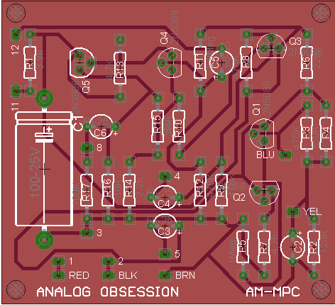
I measured this transformer.It's power transformer,normally.But freq. response is really good.18V:220V.
How can i fit this to preamp?
I think like this...
Input;
White cable to RED.
Black cable to BLK.
Output;
Red cable to YEL.
Black cable to BlU.
Other Red cable to BRN.
Am i right?
And when i measure it,i wired like this;
In XLR Pin 2 to White cable.
In XLR Pin 3 to Black cable.
In XLR Pin 1 to Out XLR Pin 1.
Red cable to Out XLR Pin 2.
Black cable to Out XLR Pin 3.
Out XLR Pin 1 to Out XLR Pin 3.
When i wire like this,there is no hum or any other noise.Really clean and good.Now should i wire like this? Or what should i do?
Thanks.
My 25 cents contribution:
1) Just a high quality 100uF/50v for C1, not a tantalum.
2) Replace all other capacitors, 3.9uF and .68uF for film types. Nowadays they are small enough and cheap enough to be considered.
And see how it sounds now?
1) Just a high quality 100uF/50v for C1, not a tantalum.
2) Replace all other capacitors, 3.9uF and .68uF for film types. Nowadays they are small enough and cheap enough to be considered.
And see how it sounds now?
ForthMonkey
Well-known member
carlmart said:My 25 cents contribution:
1) Just a high quality 100uF/50v for C1, not a tantalum.
2) Replace all other capacitors, 3.9uF and .68uF for film types. Nowadays they are small enough and cheap enough to be considered.
And see how it sounds now?
Thanks!
I used axial ROE cap for C1.And you say use film type capacitor,right? They are non polarized.Is it not problem? I thought i can use electrolytic capacitors.
ForthMonkey
Well-known member
carlmart said:Just curious: as it is now, how does the preamp sound?
I didn't finish it,yet.I'm waiting components.
ForthMonkey
Well-known member
Should i use +/-12 transformer or 2x12V transformer with this power supply?
Just 22v AC on the secondary is fine. This should be measured with charge, to see how much it would lag.
One amp type should be enough. Perhaps you may have some wall supply around that feeds around that voltage and amperage.
You will need to double it just one time probably, and let me tell you why. My usual way to compute final DC value, after diode bridge goes like this: (original VAC (22v) x 1.4) less 1.4v. Which in your case it would give you around 29v, +/- 1 or 2 volts. Doubling that would give you 58v, which is plenty enough for the LM317 regulator.
You should protect the regulator with a 40v zener between input and output. That is because you will be exceeding the maximum voltage it was designed to work for, which is 40v.
One advise: reduce C7 to 220uF and increase C3 to 100uF. You will get better noise and diminish oscillation. 3X7 regulators tend to oscillate at high frequencies when output capacitor is too high.
Add a protection diode as D2 on figure 20 in datasheet.
http://www.onsemi.com/pub_link/Collateral/LM317-D.PDF
Add protection diode D2 on phantom regulator too.
ForthMonkey
Well-known member
Thanks for explanation,carlmart.
By the way,if i can't find 22V,can i use 18V? I have some 18V.If i will use 22-24V,i have to wait...
By the way,if i can't find 22V,can i use 18V? I have some 18V.If i will use 22-24V,i have to wait...
18v is alright too, taking some precautions. How many amps?
In any case your current should be very low and nothing to worry about, except if the transformer is too small.
Yours is 18v or 18 + 18? The latter will do, the former will not.
With 18v, after rectify and filter you will get 23.8v, which you will not be able to regulate to 24v. You can use it unregulated and heavily filtered, which should lag voltage down a bit more.
For 18 + 18, joined in series, you will get 49v, rectified and unfiltered. You would have to protect the 317 as suggested for the 48v above. There will also be exceeding 25v that will have to dissipate on the regulator, so you will need a larger heatsink.
For that supply you are planning I'd suggest transformers that may go from 20 to 24 or so. They can be split of course, like 10 +10 or 12 + 12: you just series the secondaries.
carlmart said:18v is alright too, taking some precautions. How many amps?
In any case your current should be very low and nothing to worry about, except if the transformer is too small.
Yours is 18v or 18 + 18? The latter will do, the former will not if you want to regulate with 317.
With 18v, after rectify and filter you will get 23.8v, which you will not be able to regulate to 24v. You can use it unregulated and heavily filtered, which should lag voltage down a bit more.
For 18 + 18, joined in series, you will get 49v, rectified and unfiltered. You would have to protect the 317 as suggested for the 48v above. There will also be exceeding 25v that will have to dissipate on the regulator, so you will need a larger heatsink.
For that supply you are planning I'd suggest transformers that may go from 20 to 24 or so. They can be split of course, like 10 +10 or 12 + 12: you just series the secondaries.
ForthMonkey
Well-known member
18v is alright too, taking some precautions. How many amps?
It's 18V-15W.So it's 0.83A,i guess.Is it ok?
Yours is 18v or 18 + 18?
My transformer is 18V.
Now i'll use 18V xformer and after rectify and filter,i will get 23.8V,right? And it's ok for this power supply,i guess.
You should implement a proper filtering , using series and or inductors, for LC or RC. Inductors are the best, but are large and expensive.
Resistors will lag the output down.
Even if it's not something I would do, I think you will have to use a separate bridge and double that AC voltage before the regulator, as you are doing for the 48v. Either that or get another transformer.
I do not like doublers or triplers, because they double or triple the AC ripple, and it may make the ground more noisy. Particularly on large gain, low noise circuits as microphone preamps.
ForthMonkey
Well-known member
I've built this circuit without phantom power section for my Poorman's Pultec gain stage.I've used JFP for gain stage.
I found 20VAC transformer at home.With this circuit i'm getting 27.8V.Is this ok?
I found 20VAC transformer at home.With this circuit i'm getting 27.8V.Is this ok?
Similar threads
- Replies
- 14
- Views
- 1K
- Replies
- 1
- Views
- 918
- Replies
- 20
- Views
- 3K