Trident Series 65 grounding: theory and practice

GroupDIY Audio Forum

Help Support GroupDIY Audio Forum:

This site may earn a commission from merchant affiliate links, including eBay, Amazon, and others.
leigh said:
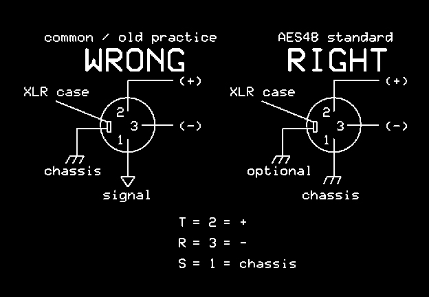
So, is this your preferred "Right" connection, or do you favor connecting the shield via a small cap (so RF still goes to chassis but low freqs do not), ferrite bead, or some other more complicated setup?

pin1problem.jpg
And those connections to chassis from the XLR case and p1 need to be AS SHORT AS POSSIBLE.  For RFI protection 2" is way beyond too much.

You use the small caps (actually needs to be a 100n ceramic), ferrites etc when you other stuff forces a single direct connection elsewhere.  Again the ceramics need to make these connections AS SHORT AS POSSIBLE
 
I am operating under the ASSumption that you do not have the will or capability to redesign the entire console, so it may not be as simple as just rewiring the jacks.

I would suggest revisiting the "pin one problem" literature. Somewhere in there they suggest how to make a tester that intentionally injects hum current into a jack ground so you can see the noise problems being created.

With one of these hum injectors, test your sundry input and output jacks for problems and to see if the simple remedies work.

Measure twice, cut once.

JR
 
Though I stopped servicing consoles years ago, this is an interesting topic to me. I worked on and installed a lot of Trident 65's, 70's, and 80's back when they were new, and even then ground noise was a known problem with these particular desks. Two quick comments.

In many cases I observed that Aux busses on these Trident desks had much more hum than the mix or group busses. This was really annoying to clients; hummy reverb sounds really bad. I personally spent many hours trying to figure out why, sometimes on my own time, but never really reached a conclusion about it. If someone else comes up with a good answer to this, I'd really like to know their findings, as this was always an annoying mystery to me.

As we know, many different things can cause ground noise. One common but not so obvious cause is the summing busses or the ground busses (which are also summing busses, in a sense) picking up ambient EMF from electrical fields in the room itself. In effect, the console motherboard acts like the secondary of a transformer; nearby power cables are the primary. (On the primary side it's all about current, so nearby mains carrying high current will tend to be the worst offenders.) The origin can be power wiring in the walls, floor, or ceiling, an overhead power line drop, nearby power strips, extension cords, a circuit breaker panel, or even a water pipe. You can test a desk for sensitivity to room EMF simply by powering up a soldering iron with a transformer in the base, and holding it beneath the console. If the room power wires are individual conductors in conduits, re-running with twisted pairs (neutral and hot) can help in some cases.
 
JohnRoberts said:
I am operating under the ASSumption that you do not have the will or capability to redesign the entire console, so it may not be as simple as just rewiring the jacks.

I would suggest revisiting the "pin one problem" literature. Somewhere in there they suggest how to make a tester that intentionally injects hum current into a jack ground so you can see the noise problems being created.

With one of these hum injectors, test your sundry input and output jacks for problems and to see if the simple remedies work.

Measure twice, cut once.

Well, I don't have the will to redesign the entire console (i.e. to redo all the input channel cards). However, modding their interconnections, and modding the master module where the summing amps live are both on the table.

So far, rewiring the jacks has done quite a bit of good. I can put together some screenshots from the frequency analyzer later, but it seems to be making any extra shield-borne noise go away. In other words, mix-bus-assigned input channels now contribute the same amount of noise to the mix output whether or not they have a line input cable patched in. This was definitely not the case before.

A hum injector sounds like a useful tool. Instant worst-case scenario, for weeding out problem spots. I'll look into it.
 
radardoug said:
Eddies grounding mod is still not satisfactory. Soundcraft provided 1 ribbon wire for the chassis ground through the ribbon. Eddies joined that to the electronics ground and put a bigger wire on it...

The chassis ground should have its own wire right back to mains earth in the power supply, not connected to anything else.

Yes, that Soundcraft mod sounds less than ideal.

In the Trident S65, they combined chassis ground and "LED ground". These connect to a separate 0V line from the power supply, which originates as the ground for the 5V supply (completely independent of the 0V line from the main +/-18V supply).

Actually, come to think of it, maybe I should try reconnecting those two grounds, within the power supply, to see what effect that has on the noise floor. When I got this board, the previous owner had already ditched the original power supply. But the schematic for the original shows that those two 0V lines were both connected to the chassis of the power supply. In my completely re-done power supply, the 5V is generated from a separate little supply, and there is no real "chassis" that physically contains the complete power supply assembly. But they could have their 0V references tied on the power supply end of things, regardless.
 
David Kulka said:
Though I stopped servicing consoles years ago, this is an interesting topic to me. I worked on and installed a lot of Trident 65's, 70's, and 80's back when they were new, and even then ground noise was a known problem with these particular desks. Two quick comments.

In many cases I observed that Aux busses on these Trident desks had much more hum than the mix or group busses. This was really annoying to clients; hummy reverb sounds really bad. I personally spent many hours trying to figure out why, sometimes on my own time, but never really reached a conclusion about it. If someone else comes up with a good answer to this, I'd really like to know their findings, as this was always an annoying mystery to me.

Glad to have you join the conversation!

You're saying the Aux sends themselves had hum on them, or that their returns had hum?

In either case, I've got a theory on why the Auxes had much more hum. As I have recently seen (with the headphone amp example above), the Trident's pin 1 can carry in hum from a connected outboard box, and the Trident is connecting that to its own signal ground. Now, 8 line inputs from a tape machine are all connecting to a common ground on the tape machine side, either to its signal ground or to its chassis. However, 8 auxes to 8 different reverbs/echos/etc will be putting 8 different ground potentials into play. More mess, more hum.

And, in addition to that "pin 1 problem" of the Trident's input and output jacks, there's another issue I found that could increase the apparent hum on the auxes: groups of jacks (all the Aux outs for example, or buckets of 8 input channels) share a common ground wire between them, draped right across the jacks themselves. More ground is not always better, and I think this is actually a design flaw. For example, say you've got 8 effect returns patched in on consecutive input channels. Even if you've only got 1 of those channels assigned to your mix bus, you would be referencing that one input signal to the ground noise contributed by the other 7 channels in that bucket.

(In fact, ALL the i/o jacks for a given input channel share that common ground line bridged across them, right at the jacks. Each input channel has 5 i/o jacks: LINE, SEND, RETURN, DIRECT out, and XLR mic in. So all those have interconnected grounds, and each group of 8 channels have interconnected grounds... which means, for example, that hum on the shield of an effect patched into channel 7's RETURN jack could show up on channel 1's line input, even if channel 7 was muted and not assigned to the mix bus.)


David Kulka said:
You can test a desk for sensitivity to room EMF simply by powering up a soldering iron with a transformer in the base, and holding it beneath the console. If the room power wires are individual conductors in conduits, re-running with twisted pairs (neutral and hot) can help in some cases.

Cool trick - my Weller iron blasts out EMF (I have to turn it off on the test bench whenever I need to actually listen to a circuit I'm working on), so I'll wave it around the console and see how much it leaks into the signal.
 
ricardo said:
And those connections to chassis from the XLR case and p1 need to be AS SHORT AS POSSIBLE.  For RFI protection 2" is way beyond too much.

One more post before I gotta run - do you have a recommendation for how to best make the connections to chassis?

Attached is a shot of the I/O jacks, in this case for the first 8 channels.

The line in jack is the one with the metal strip on top, the left jack of every pair you can see here. That metal strip connects to pin 1 of the input cable. Right above the row of jacks is that horizontal support bar. The bottom lip of that bar is only about a 1/4" inch above the jacks.

I'm trying to imagine some kind of sprung clip that I could jam in that space, that would make the chassis connection between the horizontal bar and that metal strip on the jack. Of course, I'd have to sneak in there with a Dremel or something first to grind some paint off the bottom of that chassis bar, since it's currently non-conductive.

Tricky, but IMO that beats drilling 30-some new holes through the back of the console to anchor lock nuts and wire washers to. (And that option would still require a potentially messy paint-scraping operation as well.)

Or, I could easily chassis-ground them in groups of 8, which is tempting since I don't get audible RF problems here...

If there are other off-the-shelf solutions I should know about, please do tell!
 

Attachments

  • io jacks cropped.jpg
    io jacks cropped.jpg
    434.8 KB · Views: 64
I repeat my characterization that grounds are sewer lines separate from the hot and cold clean water (audio+ and audio -).

While I do not want to second guess the old Trident design it sounds like the distant grounds are corrupting internal grounds on their way from the external jacks to the ultimate mains ground node deep inside the console.

The balanced/differential audio I/O should be able to be segregated as audio + and audio -, and then sewage (ground).

Perhaps the jack grounds need to routed separately from audio + and audio -, and certainly should find their way back to system ground without corrupting audio circuits..

Not to throw in a curve but good design may reference a single legged output to an output jack ground, but that reference wire does not need to carry the sewage flowing back the other way. To some extent current flow can be managed with relative impedances. The current will flow, just like sewage through the lowest impedance path and a ground reference will typically sense through a resistor. 

it sounds like you are making good progress, keep it up.

JR

 
Just noticed that the Mix output XLR jacks have 12k resistors wired from the + and - legs to pin 1. Why would they do that? They're not on the schematics, so not sure if they are stock or a mod somebody did.

On the master module itself, there are already 100k resistors to ground from those + and - legs of the mix outputs.
 
leigh said:
Just noticed that the Mix output XLR jacks have 12k resistors wired from the + and - legs to pin 1. Why would they do that? They're not on the schematics, so not sure if they are stock or a mod somebody did.

On the master module itself, there are already 100k resistors to ground from those + and - legs of the mix outputs.

Perhaps to discharge some noisy caps that pop when amps are plugged in...  (12k sounds lower than probably needed.)

JR
 
JohnRoberts said:
Perhaps to discharge some noisy caps that pop when amps are plugged in...  (12k sounds lower than probably needed.)

Oh, as output cap "bleeder" resistors? Maybe, but as you say, 12k is pretty low for that.

Just looked around some more, and every XLR output on the console has 12k resistors to ground. In total, that's 2 main mix outs, 2 monitor outs, 8 auxes, and 16 groups.

The main mix and monitor outs are fed by the Master module, and they both already have 100k to ground off each leg, after the last signal cap, as part of the PCB.

The other XLR outs are fed by either the Echo Return module (which does the aux sends) or the group modules. They do not have any resistors to ground after their last output caps.

I wonder if the main mix outputs got these resistors added just for output impedance consistency, or if it was an oversight/habit of whichever team was doing the back panel assembly. In any case I think I can pull them.
 
So here are some results from pin 1 lifting. All of these were captured from the Mix Out of the console, directly into a Lynx Aurora. For greater measuring sensitivity, the converter's input level was set at -10 dBV, rather than the +4 dBu that I would be using in practice. So that makes for about 12 dB of extra gain on input, and then in order to make the peaks show up in the analyzer plug-in window (since its display levels are pre-set), I am giving it another 60dB of gain within the DAW.

The first, "noise floor", measurement is with no channels assigned to the mix bus. The peaks you see are equal to or less (!) than what is measured when the console is powered off.

With the three highest-numbered (and therefore physically closest to the master module's summing amps) channels assigned to the mix buss, a 60 Hz harmonic series pops up. The largest of those, the 180 Hz harmonic, hits at about -56dB on this scale, and compensating for the ~72 dB of gain added to the signal, this means it is peaking around -128 dBFS.

The last graph shows the effect of cutting the pin 1 shield on the line inputs of these three channels. Nothing else was changed (and pin 1 has not been grounded to chassis yet).

- the 60Hz peak drops about 4dB
- the 120Hz and 180Hz peaks drop about 8dB each

Pretty effective mod so far.
 

Attachments

  • noise-floor-and-io-jack-mods.jpg
    noise-floor-and-io-jack-mods.jpg
    135.8 KB · Views: 35
leigh said:
JohnRoberts said:
Perhaps to discharge some noisy caps that pop when amps are plugged in...  (12k sounds lower than probably needed.)

Oh, as output cap "bleeder" resistors? Maybe, but as you say, 12k is pretty low for that.

Just looked around some more, and every XLR output on the console has 12k resistors to ground. In total, that's 2 main mix outs, 2 monitor outs, 8 auxes, and 16 groups.

...

I wonder if the main mix outputs got these resistors added just for output impedance consistency, or if it was an oversight/habit of whichever team was doing the back panel assembly. In any case I think I can pull them.

Having now pulled the 12k resistors to ground off the mix outputs, I think I figured out what they were for: to provide a relatively quiet output when the console is switched off. Removing them did not raise the output level at all, but I believe that now the console's output noise/hum, when switched off, is now significantly louder.
 
I suppose you might care if the console's output was left as an "open" input on another mixer. Like in a broadcast scenario where the Trident was handling the live music mix, which was then being passed to a master broadcast mixer.

It's just an idea I had, in lieu of finding another reason for those 12k resistors to be installed on the output jacks.
 
Another idea I had was it was a backup/"insurance" connection to ground, in case either the + or - signal connection failed somewhere between the master module's Molex pin outs and the output jack.

In the case of such a failure, rather than leaving that leg hanging, referenced to nothing, the console would still be putting out a balanced signal, with actual signal on one leg and a reference to ground through 12k on the other leg.
 
leigh said:
Another idea I had was it was a backup/"insurance" connection to ground, in case either the + or - signal connection failed somewhere between the master module's Molex pin outs and the output jack.

In the case of such a failure, rather than leaving that leg hanging, referenced to nothing, the console would still be putting out a balanced signal, with actual signal on one leg and a reference to ground through 12k on the other leg.

In that case it wouldn't be impedance balanced, but 12k are better than open, it's true, but unlikely to be that, I mean, if you have something broken why would you expect to work properly, with 100k or even more it's ok as bleeder, and still safe in that case, higher noise but who cares if a broken output is noisy, it's already broken, too good it didn't broke anything else, let's fix it (or ask to be fixed) and use another output till is fixed.

JS
 
joaquins said:
...I mean, if you have something broken why would you expect to work properly...

Yeah, again, just guessing here. Since I still don't understand why those 12k's to ground were on the output pins.
 
leigh said:
joaquins said:
...I mean, if you have something broken why would you expect to work properly...

Yeah, again, just guessing here. Since I still don't understand why those 12k's to ground were on the output pins.

Do not waste brain cells on this distraction... if there was a valid reason for them being there it will reveal itself over time, if not it won't.

JR
 
JohnRoberts said:
Do not waste brain cells on this distraction... if there was a valid reason for them being there it will reveal itself over time, if not it won't.

Well, if you're saying it's safe to ignore, then I believe you. I want to clean up the grounding in this board, but I don't want to yank something out and then regret it later, just because I didn't understand it at the time. In any case, now the output jacks look like this - that's pin 1 to chassis, and no more 12k resistors connecting pins 2 & 3 with pin 1.

PS: It may look like pin 1 is also going to signal ground via the blue and yellow cables, but those cable shields are not connected to anything on their other ends.
 

Attachments

  • output-jacks_crop.jpg
    output-jacks_crop.jpg
    44.9 KB · Views: 48

Latest posts

Back
Top