Simple 600 ohm test load

GroupDIY Audio Forum

Help Support GroupDIY Audio Forum:

This site may earn a commission from merchant affiliate links, including eBay, Amazon, and others.

ruffrecords

Well-known member
Joined
Nov 10, 2006
Messages
16,239
Location
Norfolk - UK
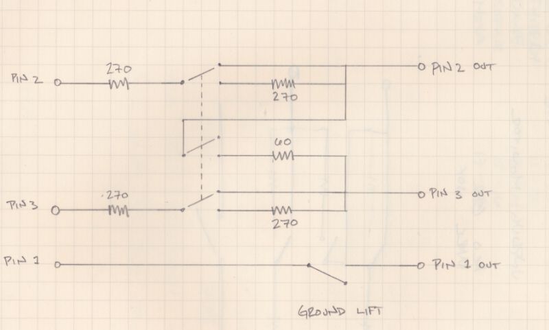
It is often necessary to have a 600 ohm load available when testing balanced outputs. Testing their maximum output into a 600 ohm load can also be a problem, especially if you are using  something like RMAA and an ADC that will not cope with input levels of +20dBu or so. So I designed a simple switched attenuator that presents either a 600 ohm load or or provides a 20dB pad with a 600 ohm load simply by flicking a switch. All you need is half a dozen resistors, a couple of XLRs and a DPDT toggle switch. I built mine in a small die cast box holding the output XLR and the switch. The input XLR was on a flying lead so I can plug is straight into an output and plug my test gear into the die cast box. The schematic is attached.

In the 0dB position , R1 and R4 are shorted out so the input is connected directly to the output. R2, R3, R5 and R6 provide a 600 ohm balanced load. In the -20dB position,  R2 and R5 are shorted out and R1 and R4 are in series with the input. These, with R3 and R6 provide a 20dB balanced attenuator and a 600 ohm load. What I like about the design is that it does not need any weird resistor values yet is provides exactly 600 ohms load and 20dB attenuation. The 30 ohm resistor I made from a pair of 15 ohms in series.

Cheers

Ian
 

Attachments

  • 600ohmswitchedload.png
    600ohmswitchedload.png
    18.7 KB · Views: 219
The 30 ohm resistor I made from a pair of 1 ohms in series.
That must be a typo.

There should be no ground connections in a balanced circuit.
 
The 30 ohms is made of two 15 ohm resistors. I have corrected the typo in the original.

You are both right, the screen/ground connection is not necessary. This is muddled thinking left over from another issue I was tackling. In a separate project I had a 'Neve trick' output  attenuator using a single pot working on a transformer balanced output. When this control is fully off it shorts its hot and cold outputs together but they are both still connected to the cold source. Some electronically balanced inputs exhibit a rather poor CMMR under these conditions and register an attenuation of only 40dB. Part of the reason is that the inputs are differential rather than balanced and need a ground reference to work properly. using a balanced attenuator solves the problem but I still had the need for the ground reference stuck in my head.

Cheers

Ian
 
Speedskater said:
But R3 and R6 are still connected to the pin1 shield.  This pin1 is not an audio circuit common or shield.

Sorry, you lost me. Pin 1 is connected to the shield and as often as not to audio 0V.

Cheers

Ian
 
It's been 20 years now since the first paper and designers still get it wrong.

Pin 1 Revisited
Neil Muncy called our attention to the Pin 1 problem (the improper termination of the shield of audio wiring to the circuit board rather than to the shielding enclosure) in his classic 1994 paper, reprinted in the June 1995 Journal of the AES. When he wrote his paper, most commercially available audio gear had pin 1 problems. It was, indeed, difficult to find equipment without it -- even the most prestigeous consoles had serious pin 1 problems! Over the next decade, the better manufacturers redesigned their products to correct their mistake, but sadly, many have not done so.


http://www.audiosystemsgroup.com/Pin_1_Revisited.pdf
 
Speedskater said:
It's been 20 years now since the first paper and designers still get it wrong.

I know that, but:

1. pin 1 is connected to the shield of the cable.

2. The chassis of the equipment does ultimately get connected to signal 0V

3, In the actual implementation of the test load , one connector is a flying lead with the screen connected to pin1 and the other end is a connector in a die cast box. The screen of  the incoming cable is connected to pin1 of this connector and also to the box.

Are you suggesting something is wrong with that implementation?


Cheers

Ian

P.S  http://www.ianbell.ukfsn.org/EzTubeMixer/docs/EzTubeMixer/SimpleMixer/grounding101v2.pdf
 
While I didn't reread the entire paper, for the most part it's an excellent paper with this one exception.

Since the power supply is nearby, then this is the place to connect the
signal 0V to the common point. Since we only want to connect these three together at
one point this means the signal 0V must not be connected to chassis or screen
anywhere else.


The correct connections are:
a] AC power should connect to the chassis near it's inlet.
b] Each XLR connector should connect to the chassis at each connector.
c] The audio circuit common should connect to the Main Audio Ground (MAG).
d] The power supplies should connect to the Main Audio Ground (MAG).
e] The Main Audio Ground (MAG) should connect to the chassis near the input/output jacks.

Yes all these different functions are galvanically connected, but each has a proper location for it's chassis connection.
 
MAG is a DIY Audio forum thing.
http://www.diyaudio.com/index.php
It saves a lot of writing about the star point and the connection to the chassis.
 
Connecting the attenuator to "ground" has the advantage of attenuation common-mode signals. But then the matching of the resistors becomes significant, or CMRR will be poor. I'd probably make it floating too.

Samuel
 
Speedskater said:
MAG is a DIY Audio forum thing.
http://www.diyaudio.com/index.php
It saves a lot of writing about the star point and the connection to the chassis.

I have no problems with TLA provided they are first defined. I searched diyaudio.com and I can find no such definition. Given Speedskaters point e) in his post, this sounds like it is aimed at unbalanced Hi-Fi equipment, especially integrated power amps, rather than balanced pro gear.

Cheers

Ian
 
I don't know what main audio ground is, but I don't think Ian's diagram would cause problems in most cases. Besides, I'm sure he's already using it with no problems.  Remember, it is a separate box (adapter?) for testing how other equipment handles a 600R load, it's not meant to be permanently in place. 
Anyway, to float it, could you simply connect the shunt R's between pin 2+3?  I guess the thing is to find what will work in all cases? Unbalanced, trafo balanced, impedance balanced, electronically balanced?
 
What am I missing? It seems to have two more 12-cent resistors than it really needs to have.

While hacking I added switched ground so ground-fussy users can suit themselves.
 

Attachments

  • 600ohmswitchedload-prr.gif
    600ohmswitchedload-prr.gif
    6.4 KB · Views: 95
PRR said:
What am I missing? It seems to have two more 12-cent resistors than it really needs to have.

While hacking I added switched ground so ground-fussy users can suit themselves.


LOL, well spotted. I struggled for ages working out that switching scheme when the obvious eluded me. Thanks PRR.

Cheers

Ian
 
ruffrecords said:
PRR said:
What am I missing? It seems to have two more 12-cent resistors than it really needs to have.

While hacking I added switched ground so ground-fussy users can suit themselves.


LOL, well spotted. I struggled for ages working out that switching scheme when the obvious eluded me. Thanks PRR.

Cheers

Ian

I did saw that when you just posted it, I thought you didn't want the output to be open and just for two resistors would be fine to waste... Well, now PRR mentioned it you can save your 24 cents.

JS
 
Here is an updated/simplified  version. Note the two 30 ohm resistors have been repalce by standard resistors of 27 and 33 ohms.

Cheers

Ian
 

Attachments

  • 600ohmswitchedloadV2.png
    600ohmswitchedloadV2.png
    16.4 KB · Views: 82
oops - I think you have taken the "load" aspect out of the circuit now…

looks like in one switch position input is shorted straight thru to the output…

the other way is a pad with a k factor of exactly 10 - so 20db.

i just sketched this out quick - take a look - with a 3PDT switch you can turn the pad on or off and switch that shunt out as well… oh and if you want to put the ground reference in-between 2 shunt resistors - that should effect switching at all...

and then a SPST if you want to lift the ground - but the inputs would have to be isolated from the chassis for this to work...

 
mutterd said:
oops - I think you have taken the "load" aspect out of the circuit now…

looks like in one switch position input is shorted straight thru to the output…

the other way is a pad with a k factor of exactly 10 - so 20db.

i just sketched this out quick - take a look - with a 3PDT switch you can turn the pad on or off and switch that shunt out as well… oh and if you want to put the ground reference in-between 2 shunt resistors - that should effect switching at all...

and then a SPST if you want to lift the ground - but the inputs would have to be isolated from the chassis for this to work...


He didn't took the load out of the circuit, in fact, you sort of did that... If you look at the load seen by the source (I told my professor sources don't have eyes but you follow me) in Ian's circuit the source always see 600Ω assuming the load after that is much grater. In your circuit the source see the load after that plus 540Ω in one position, with the same load which maybe is 10k or so, the load is far from being 600Ω. When you add the attenuator, the source now see the 600Ω from the attenuator (in parallel with the 10k load, as if it's not there for the case) plus the 540Ω again, so 1140Ω total.

The thing is the load is what the source is driving, with it's voltage output is trying to put a current through 600Ω (is what we want). In your circuit the current would flow through a higher resistance. I hope you see the point here.

JS
 
Back
Top