


saint gillis
Well-known member
Hello, I've made a combo Pultec with an MEQ5 and a EQP1A in the same 2U 19'' rack :
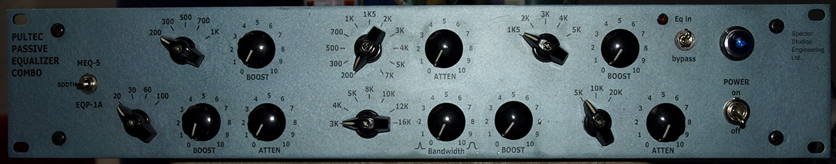
We can choose to use only one of each or booth at the same time, there is only one input and one output, the idea was to save space and being able to use these 2 wonderful eqs at the same time in the same circuit, thus saving 2 transformers
Of course it was difficult to use tube amplifiers because of space so I choose 990C op amps, here is the block diagram :
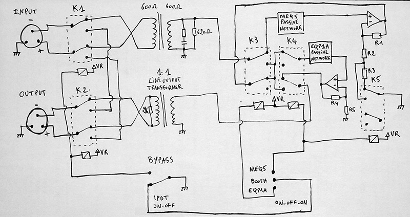
Never more than 2 relays at the same time, so very low power consumption, there is a trick to stay everytime in unity gain (because of transformer loss etc).
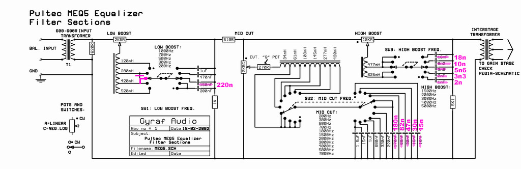
Here is the corrected schematic of the MEQ5 passive network, I verified all the curves with RMAA, looks great (and sounds great), thanks one more time to Gyraf for the ressources he offers to us! :
On the block diagram, R2 & R5 are in fact a resistor + a trimmer to adjust unity gain, R3 is another trimmer... I used DC servos to remove dc from the op amps outputs and kind of JT-OLI-2 at the output of each op amp, and on grounded side of the output transformer, just like on Jensen's schematics.
I used Sowter 5069 on input and Lundahl 2811 on output which showed a little bit of distortion on square waves (because of its little size I guess) but I m very satisfied with the sound and the linearity is quite perfect. The inductors come from Don Audio in Germany (thanks to Aaron, great guy).
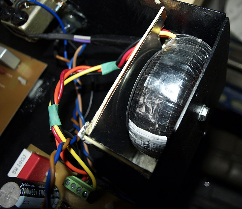
When testing the unit, it was a bit noisy when boosting high frequencies on the MEQ5, it came from the PSU toroidal transformer, but finding the right place for it was the solution (right back corner of the rack) , and adding a sheet of mu-metal made the unit perfectly silent any frequency at full boost :
I don't share pcbs because I used a kind of custom DOA footprint, but the block diagram tells everything...
It is amazing to see that a design from 1951 (maybe even before) remains so terrific! These 2 eqs together are simply the best
We can choose to use only one of each or booth at the same time, there is only one input and one output, the idea was to save space and being able to use these 2 wonderful eqs at the same time in the same circuit, thus saving 2 transformers
Of course it was difficult to use tube amplifiers because of space so I choose 990C op amps, here is the block diagram :
Never more than 2 relays at the same time, so very low power consumption, there is a trick to stay everytime in unity gain (because of transformer loss etc).
Here is the corrected schematic of the MEQ5 passive network, I verified all the curves with RMAA, looks great (and sounds great), thanks one more time to Gyraf for the ressources he offers to us! :
On the block diagram, R2 & R5 are in fact a resistor + a trimmer to adjust unity gain, R3 is another trimmer... I used DC servos to remove dc from the op amps outputs and kind of JT-OLI-2 at the output of each op amp, and on grounded side of the output transformer, just like on Jensen's schematics.
I used Sowter 5069 on input and Lundahl 2811 on output which showed a little bit of distortion on square waves (because of its little size I guess) but I m very satisfied with the sound and the linearity is quite perfect. The inductors come from Don Audio in Germany (thanks to Aaron, great guy).
When testing the unit, it was a bit noisy when boosting high frequencies on the MEQ5, it came from the PSU toroidal transformer, but finding the right place for it was the solution (right back corner of the rack) , and adding a sheet of mu-metal made the unit perfectly silent any frequency at full boost :
I don't share pcbs because I used a kind of custom DOA footprint, but the block diagram tells everything...
It is amazing to see that a design from 1951 (maybe even before) remains so terrific! These 2 eqs together are simply the best


")