Starting a modular console - CAPI/GDIY 508 rack build

GroupDIY Audio Forum

Help Support GroupDIY Audio Forum:

This site may earn a commission from merchant affiliate links, including eBay, Amazon, and others.
So here's where I get confused on output grounding.  I think I have it figured out, but I would much rather bounce my understanding off of those with actual knowledge.

On the Classic API site, Jeff states the following re: the input grounding:

With the introduction of the Rev B version of this backplane, all input shield “options” have been removed. All of these shield connections now go directly to the Chassis ground plane.

And output grounding:

"The outputs from the relay PCB and the module slot itself have their shield connections made to the Chassis plane. This is the most common and safest way to handle this connection since it could not be fully user selectable. More often than not, the output cable’s shield will float and make no connection to any ground plane at the output of a 500 series module. Please be advised, I am not recommending to always do this. Each installation will be different."

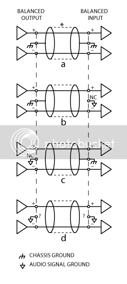
I've been trying to understand the underlined part.  Also, for reference, here is figure 5 from the RANE notes:


http://www.rane.com/note151.html

For fully balanced, the Rane notes state:

Fully balanced systems (left column in Figure 5) provide the best performance when both ends of the shield connect to units with chassis-grounded shields (Figure 5a). When units with signal-grounded shields are encountered, disconnect the shield at the signal-grounded end (Figures 5b & 5c). This keeps the induced shield currents out of the audio signal ground.

Here starts the rambling part.

Based on my understanding of the Rane notes, if both ends of the connection are chassis grounded, then I would want to connect the ground wire at both ends.  So, any connections between 508 backplanes within the console (i.e. mic pre out to eq in), I would want to use the ground, as both connections are chassis grounded.

For connections to other gear, like an A/D converter, DAW interface, external compressor, etc... whether or not to connect the shield would be dependent on the grounding scheme of the interfaced gear.  If it's chassis ground, then connect ground at both sides (module slot output and A/D converter input, for example).  If one of the two is signal ground instead of chassis ground, then float the ground wire at the signal ground connection.

Do I have that right so far?  If so, why float the output cable shield at the output of the 500 series module, since it's a known chassis ground?  I realize that is just one option, and Jeff clearly is not saying it's right for everything, but I'm trying to understand what is being accomplished by leaving the module output ground floating.

Hopefully all that made sense, and, once again, many thanks for all help provided.

Thanks,

Keith
 
I've got one in the works. Rest assured, progess is being made. I've been selling off a good deal of my "store bought" gear to fund, and unfortunately the day all my funds cleared was the same day Jeff went on vacation... But he mentioned on the shop's away message that he was testing a compressor on said vacation as well, so who the hell cares about a short delay.

One thing I would like input on: patchbay. I've decided to forego the db25 i/o on the rear panel and do internal wiring to a patchbay, as inspired by Gary's sphere sidecar. It made me realize just how many soldered interconnects there can be, and adding in db25 connectors increases the number exponentially. The hell with that. The only db25 connectors I will need is patchbay > orion 32 i/o.  The orion was delivered yesterday, pretty excited. About time to say goodbye to the ol' digi003.

Anyways, patchbays. Right now I'm planning to get the audio accessories 96pt TT solder patchbay from Redco @ $375. Price point is good, reputation seems good, etc... it should offer enough to allow for some future growth.  Thoughts?
 
This post will be a "what's been happening" post, the next will be a "what's next".

First off, if you ever get the bright idea to start building a console, have a few grand of walkin-around money already stashed aside, above and beyond what you "think" it's going to cost.  Here's a tip: you have to think about it one order at a time, and avoid looking at "order history" pages at either Mouser or Classic API... when you look at how much you've spent in aggregate over a short, say, 2 month period of time, you might start doing foolish things such as "considering your budget" and "seriously asking yourself if you can afford this". 

While design ideas, signal flows, feature sets, etc... have been constantly evolving as I get deeper into this project, one thing that has stayed constant is the need for a crap load of gar2520's.  So, I picked myself up a 50 pack of pcb's:


One thing that I find kinda funny:  prior to getting started in DIY, I could never think of any legitimate business that would have a need for the tiny little zip lock bags... oh, how we learn.

I had built a few of these in kit form before, and most of my assembly time was spent sorting and bending components.  The only efficient way to mass produce these things is to prep everything up front.  A snowy Saturday and season 4 of Breaking Bad on Netflix made this tedious chore much easier.


Everything pre-bent and clearly labeled, 50 pairs of transistors paired.

Now I can work through batches at a time.  I find an hour or two every other day keeps me from going insane stuffing these things.  I've been doing batches of 6-12, get them all about halfway, then completely finish one of the batch out and test to make sure I didn't screw anything up in the first half of stuffing. 


I think I'm up to 24 or so by now.  Just need to keep my head down and power through.

I'm using 4 channel boards from Hakanai for basic architecture of the summing section.  These are 4 channel boards with 2520 line receivers, level, pan, and stereo bus.  The Mark I of the mixer will be 24 channels total; 12 with faders and pan, and another 12 line in from DAW.  The line in's will be 4 mono with level and pan, 4 stereo with level.  Stereo bus will feed into a 2-ACA (I forgot to order one damn resistor for the 2ACA, which will hopefully arrive by the end of the week so I can start some testing).  More on signal flow and whatnot in my next post.

Here's one of the Hakanai boards stuffed: 


And the group shot:


Things are coming right along.  I'll outline what's next in a post either tonight or tomorrow.


Now, for the "what's next".

I need to get this thing from a jumble of different parts into one home.  I have a good friend who does CNC woodwork for a living to make the frame, but I need to get my fader area size and layout sorted to move forward with that.  So that is my next goal.

This is my current idea, and I'll go in to the subsections below.


1) Mic/Line

General idea of channel signal flow:


I've been playing around with a couple of Classic API Plug in Relay boards, and for my knowledge level, they are great.  All I need to do is connect the VC pin to ground, and a noise-free, seamless switch.  The physical connections of the rest of the pictured signal flow (outside the mic/line relay) are for a later topic.

2) Fader and pan

As part of "learning by doing", I've decided to design my own pcb for the fader amp, pan, mute and solo sections.  I've been spending a decent chunk of time trying to learn KiCad.  I have a schematic for a majority of the PCB drawn out on paper and have been transferring that to KiCad, learning as I go along.  I'll post schematics once I get them fully transferred.  For the time being, here's a block diagram.


The "from line receiver" will pick up at the fader point on the Hakanai boards, Out L and R will go back to the Hakanai boards bus.

Pan Options:  I still need to do more research on this.  Simplest would be a 10k linear pot.  However, there's also dual 10k slugged linear, and then I just noticed that Colin has 10k log/alog pots w/ detent, so that's something else to consider.  Feel free to toss your advice in on this.

3) Mute and Solo

Going back to the before mentioned Plug in Relay boards, all I need to do is connect VC to ground.  Simple enough for Mute, not so much for solo.  The below is what I've come up with for a basic mute/solo logic, controlling the "Mute" in the above block diagram. 


I have a lot more detail to go in to and questions to ask, but I wanted to post up my general ideas for feedback.  These posts can take a little while to write, so I'm trying to avoid rambling and keep it simple.  There will be much rambling to come.

Thanks.

Keith.
 
john12ax7 said:
For the patchbay I would strongly recommend getting a db25 one instead of one you have to solder. Makes things so much easier.

I've decided to bypass the db25 i/o on the console backpanel and go with an integrated patchbay like pictured in Gary's Sphere sidecar thread:

http://groupdiy.com/index.php?topic=45733.msg681578#msg681578

This avoids wiring to the db25 outs and wiring up db25 cables, 3 solder joints down to one.  The patchbay and DAW interface (Antelope Orion 32, all DB25 i/o) will live on top of eachother, so I will have to wire db25 to patchbay to connect them, and that's it.  Everything on the console can go directly to it's necessary patch bay solder point.

I need to put together an updated picture of overall physical layout.  Just assume it mirrors the Sphere sidecar for the time being.
 
Krcwell this is great! Keep up!

Just watch on one small detail!
If you put the patchbay next to the mouse and keyboard, you'll have your patchbay cables most of the time laying on the keyboard and annoying you when you want to type. I would put the patchbay in the top position, then Orion below that, and the rest of the units (4U space) below.

:)
 
shot said:
Just watch on one small detail!
If you put the patchbay next to the mouse and keyboard, you'll have your patchbay cables most of the time laying on the keyboard and annoying you when you want to type. I would put the patchbay in the top position, then Orion below that, and the rest of the units (4U space) below.

:)

Good eyes!

I've been thinking about whether the patchbay would be better at top or bottom, and have concluded that I'll just need to wait and see. Left side of patchbay will be inserts 1-24, right side will be insertable goodies. I have some 12" and 18" patch cables being delivered with the patchbay on tuesday, so I can see if there would be clearance in the mouse/keyboard area. My overall hope is that the console minimizes my need for a mouse and keyboard!
 
I spent some more time fiddling with KiCad today, and figured I should post my work-in-progress schematic.  This fader amp and pan are a copy of schematics Hakanai posted for a project he was working on.  He was kind enough to answer some questions via e-mail on adapting to my needs using the 10k log Alps faders I picked up from AML. 

That being said, I have somewhere between a very basic and not-at-all understanding of what's going on in this circuit... but I am good at copying.


To better understand the above, B is connected to O as default on the CAPI relay board, and when VC is connected to ground, A is connected to O.  I still need to draft up the mute/solo switches that go to the VC pin on the CAPI relay board. 

I also need to figure out how to supply power to both the relay boards and the LED illuminated pushbutton switches for mute/solo. 

But, for the time being, how does this look?
 
Keith..  (sorry about that been a long day lol)

Keep your Audio and Logic (relay)  grounds separate
backto  the PSU star point. Tthis will help keep dirty  relay noise
out of your clean audio signal.
BTW.. You can use your logic Gnd for LEDs as well.

Best

GARY
 
gar381 said:
Don

Keep your Audio and Logic (relay)  grounds separate
backto  the PSU star point. Tthis will help keep dirty  relay noise
out of your clean audio signal.
BTW.. You can use your logic Gnd for LEDs as well.

Best

GARY

It's Keith, but....  :)

I'm working with the GDIY psu which has both chassis and ground pins that tie to star ground at the psu. Would I wire relay and led ground to chassis? Or am I totally off on concept.
 
Krcwell said:
It's Keith, but....  :)

Keith.. sorry about that!! It was a long day and I was totally burnt :-[

Krcwell said:
I'm working with the GDIY psu which has both chassis and ground pins that tie to star ground at the psu. Would I wire relay and led ground to chassis? Or am I totally off on concept.

If you can get the relay/led feed to the star by itself would be the best.
If not the  chassis would be the next bet but at any rate keep it off audio gnd.

Best

Gary
 
Very excited to see this completed and also wishing that i had the means to do it myself.
 
gar381 said:
Keith..  (sorry about that been a long day lol)

Keep your Audio and Logic (relay)  grounds separate
backto  the PSU star point. Tthis will help keep dirty  relay noise
out of your clean audio signal.
BTW.. You can use your logic Gnd for LEDs as well.

Best

GARY

My first thought was, I have 7 core cable running from my GDIY floorbox PSU to the console, but I'm only using 5: +16v, -16v, +48v, ground, chassis.  The other 2 are there for 24v... I could just extend one of those extra cores to the star ground at on the PSU side and use that as my ground for the relays and LED's.

...and THEN (picture Garth when he's describing how he'll get the Wayne's World feed of Crucial Taunt's live performance to the satellite dish on the back of  Mr. Big's limo...)

I realized that the thing that's been nagging in the back of my head, the fact that I would need to expand my power supply eventually, was front and center.

Realistically, I can't power 12 mic pres, 12 eqs, 4 compressors, and 36 extra 2520's in the summing section, with one floorbox PSU.  So I've been thinking a dual GDIY PSU in a 2U or 3U rack piece... I have 16U of rack space on the lower right of the desk that the console will sit on, that would be a good spot.  Why not then throw a separate small PSU in the case for the relays and LED's?  Keep all the relay and LED noise entirely separate on it's own PSU, only connecting at star ground on the racked PSU case. 

Thoughts?
 

Latest posts

Back
Top