voltage regulators parallel connection ?

GroupDIY Audio Forum

Help Support GroupDIY Audio Forum:

This site may earn a commission from merchant affiliate links, including eBay, Amazon, and others.
Kingston said:
To sum it up for you once more, heater regulation is pointless, even unsafe.

Amen to that

whats the tolerance for heaters. does it ned to be dead on 6.3 V or its multiplies...


Kingston said:
buildafriend said:
Btw, while we're on it I'm interested a DC heater circuit with paralleled 3080's.

That's like driving your cows to pasture in the front seat of your Ferrari when all you needed to do was to open the door for them. LT3080 is practically a super regulator on a chip. They are interesting for very high end audio signal chain applications. PSU's with 12-24VDC rails for your opamps and DOA's.

See the heater circuit here, http://www.michaelkingston.fi/files/Drive-1_schematic_rev2.1.pdf
It's all you need for high end tube performance and it's far more safe compared to regulated.
Here's a version with regulator: http://www.michaelkingston.fi/files/Drive-1_schematic_rev1.9.pdf
It started failing after two years and eventually the regulator chip died. It didn't help that the heat sink was huge, TO220 and big-watt do not go in the same sentence. Full story with images and measurement data in the thread: http://groupdiy.com/index.php?topic=41509.0

To sum it up for you once more, heater regulation is pointless, even unsafe.

PS. Don't use the high voltage part of that schematic for anything. It's clumsy and expensive. I've since designed something far more efficient with very low parts count and better performance.

The Drive-1 looks looks bad a**.  :eek: Are you using a regulator for relays?

Anyway, I agree it's over engineering to have DC regulated heaters but I've had nightmare builds before on PCB's where you just can't win. I'll pay the extra few bucks for my cows so I don't have to worry. I used an LD1084.

I've also used strait up AC twisted pair from the iron with 2 100 Ohm resistors to ground and gotten great results.
 
buildafriend said:
Are you using a regulator for relays?

Of course. No other way to do it. The required current can be from 0 to N times the number or relays you have switched on at any given time.

That's not the case with heaters where current draw is constant and forever.

buildafriend said:
I'll pay the extra few bucks for my cows so I don't have to worry.

But you do have to worry now. Instead of simply calculating  one dropping resistor resistance, you now have to calculate a correctly sized heatsink and hope it never gets too warm up in there. Performance is the same for both as are the layout requirements.

 
kambo said:
whats the tolerance for heaters. does it ned to be dead on 6.3 V or its multiplies...

Tube datasheets will tell you. It's usually +-10%, sometimes more. They are not fussy at all. emrr here on the forum has mentioned some wildly bad heater PSU voltages for his gear that should have made things fail and perform badly, but didn't and lasted for decades.
 
kambo said:
so i am totally fine with 6VAC or 12VAC etc...

Indeed. or VDC. In fact 12.6VDC is often done with the ultra cheap LM7812 in mass produced gear. Behringer and Art for example with their pointless fart-tubes there for a show only. In fact I opened a Vox Tonelab unit and not only did it have 12VDC for heaters, but the same source for plate also(how's that for a starved plate!).

buildafriend said:
Kingston, what relay do you prefer to use?

For signal path whatever Omron G5V-2 variant or clone or close equivalent I find. Usually 12VDC but I once shared a heater 6.3VDC supply for 5VDC relays and they are happy. Like heaters they are high tolerance (see datasheets). The rare cases of high voltage switching I've done is with reed relays. Just go to mouser or digikey and select whatever specs/size/price best serves the purpose.
 
Kingston said:
See the heater circuit here, http://www.michaelkingston.fi/files/Drive-1_schematic_rev2.1.pdf
It's all you need for high end tube performance and it's far more safe compared to regulated.
Here's a version with regulator: http://www.michaelkingston.fi/files/Drive-1_schematic_rev1.9.pdf
It started failing after two years and eventually the regulator chip died. It didn't help that the heat sink was huge, TO220 and big-watt do not go in the same sentence. Full story with images and measurement data in the thread: http://groupdiy.com/index.php?topic=41509.0

To sum it up for you once more, heater regulation is pointless, even unsafe.

Passive version looks interesting although i'm not sure remaining ripple wouldn't cause problems in all applications. Another things is i don't see PTC thermistors used in this kind of gear, is there any particular reason for this? Controlling inrush current is good for sure, especially in diy projects where we play with the circuit a lot before finishing it.
I started using LDO LM1085 regulators for the heaters, it takes a little more calculations and just in case heater tap is split at ~7V and 8,5V (7V works ok), also has a lot more power than needed. Results are much better this way because regulator never has more than ~65 degrees C, ripple is very low in uV.
I never try to get more than 1A at 6,3V from it, that is with heatsink and carefully set dropout voltage. Sometimes voltage is set a little lower than 6,3V to give regulator more volts to function properly. I know it sounds like a lot of work for regulator, but once i got a few running new ones are easy to make.
Don't know why this would be unsafe if i make sure regulator works under all conditions and doesn't heat much. PTC looks very nice, might try passive version with it and use regulators only for phantom and utility only. Takes less work and looks more durable.

 
My3gger said:
i'm not sure remaining ripple wouldn't cause problems in all applications.

It won't. I seem to recall it was 20mA with big caps, maybe 20000uF. You have to fail layouts pretty bad in order to have that stir any trouble.

My3gger said:
Another things is i don't see PTC thermistors used in this kind of gear, is there any particular reason for this?

I can't find them anywhere with sizes fit to these applications. The ones I've managed to find can run maybe a headphone amp before burning up.

I would like to use them everywhere. I have many big PSU transformers and worry about safety often. If you have a stable EU source, don't hesitate to let us know.
 
hey Kingston,


reading about MJE18004G from your PSU,
do you really need Switch-mode NPN Bipolar
Power Transistor ?


thanks
kambo
 
Kingston said:
See the heater circuit here, http://www.michaelkingston.fi/files/Drive-1_schematic_rev2.1.pdf
It's all you need for high end tube performance and it's far more safe compared to regulated.
I can't say I wholeheartedly agree. Indeed, "the less components the less possible failures" applies somewhat, but I see a major flaw there; if one of the filaments blows, the voltage increases, consequently taking the other filaments. There should be some kind of crowbar protection.
Here's a version with regulator: http://www.michaelkingston.fi/files/Drive-1_schematic_rev1.9.pdf
It started failing after two years and eventually the regulator chip died. It didn't help that the heat sink was huge, TO220 and big-watt do not go in the same sentence.
That just proves that there was a flaw in the implementation. Probable cause is unsufficient heat extraction. You can't blame the principle when there is a fault in implementation. Indeed TO220 dissipating 5W is a challenge, particularly regarding how heat is extracted from the box - that's the main issue: calculations of the heatsink are generally good, but forgetting the heat increase inside the box is a very common overseeing.
To sum it up for you once more, heater regulation is pointless
Agreed, but once the decision of powering them at DC is made, practical considerations make regulators a tempting option. There are other options, such as capacitance multiplier, but the component count is not as favourable
, even unsafe.
Any design is potentially unsafe; it's a matter of risk evaluation.
 
Left unsaid:

1. 5V Switch Mode Power Supply, turn the output trim up to 6V....advantage:efficient
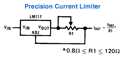
or 2. LM317 current regulation per tube; per pair;parallel;series heater.(just don't yank a tube out with a parallel setup as the remaining tube gets all the current)....advantage:brings the tube up slowly
Precision-Current-Limiter-Schematic-Circuit-LM317-LM338-LM350.png
 
Piedwagtail said:
Left unsaid:


or 2. LM317 current regulation per tube; per pair;parallel;series heater.(just don't yank a tube out with a parallel setup as the remaining tube gets all the current)....advantage:brings the tube up slowly
Have you actually put that in practice? Powering any kind of incandescent device with a CCS is prone to thermal runaway. When the resistance increases with temperature, the voltage increases, which in turn increases the temperature...
I wouldn't do that.
 
abbey road d enfer said:
I can't say I wholeheartedly agree. Indeed, "the less components the less possible failures" applies somewhat, but I see a major flaw there; if one of the filaments blows, the voltage increases, consequently taking the other filaments. There should be some kind of crowbar protection.

Heater failure is extremely rare. I have never heard of one, and I seem to recall very little evidence here on the forum either. "Far too rare to care" was my risk evaluation compared to a relatively easily achievable heat dissipation issue with regulators.

abbey road d enfer said:
You can't blame the principle when there is a fault in implementation. Indeed TO220 dissipating 5W is a challenge, particularly regarding how heat is extracted from the box - that's the main issue: calculations of the heatsink are generally good, but forgetting the heat increase inside the box is a very common overseeing.

I wasn't so much blaming the principle, but trying to point out it's so hard to get right might as well default to other options. TO220 dissipating 5W is relatively easy, but there were already mentions of LM338 with its 5 amps. These type of regulators commonly have a minimum input output voltage difference of 3V, which immediately takes us to 15W and beyond.

kambo said:
reading about MJE18004G from your PSU,
do you really need Switch-mode NPN Bipolar
Power Transistor ?

It also says TIP50. Whatever very high voltage NPN. I did mention earlier it's clumsy, expensive. No, you don't need 8X 100uF/450V caps!  :eek: I've designed a much cheaper and better performing high voltage PSU with MOSFET and a single electrolytic since this one.
 
Kingston said:
Heater failure is extremely rare. I have never heard of one, and I seem to recall very little evidence here on the forum either. "Far too rare to care" was my risk evaluation compared to a relatively easily achievable heat dissipation issue with regulators.
Indeed it is very rare; I believe I had two cases in 50 years. It's so frustrating, particularly when you're a 16 years old that has slaved for weeks to buy a set of El34 and finds one doesn't glow anymore; I guess I'm traumatized... One has his own risk evaluation depending on an infinity of factors. My own take is taht I'd rather have one regulator for each filament; that would run the regulators far from their limit and spread the heat. 
I wasn't so much blaming the principle, but trying to point out it's so hard to get right might as well default to other options. TO220 dissipating 5W is relatively easy, but there were already mentions of LM338 with it's 5 amps. These type of regulators commonly have a minimum input output voltage difference of 3V, which immediately takes us to 15W and beyond.
Indeed. I would use the 338K only with a huge heatsink and plenty of air circulation.
 
something like this ?
(for B+)
http://www.solderingpoint.com/projects/mosfetps/mosfetps.php

 
X1-3 in that design shouldn't be connected to the HV secondary center tap, well, it must not be connected to there or it WILL blow the transformer. Heaters fuse it wrong, or should have two if used, since a short between X3-3 and X3-2 wouldn't be protected but by the  fuse at the input.

Be careful with that circuit, as I mentioned, have at least two problems with protection.
JS
 

Latest posts

Back
Top