


somorastik
Well-known member
- Joined
- Dec 12, 2008
- Messages
- 47
Hi and all the best for the DIYers ")
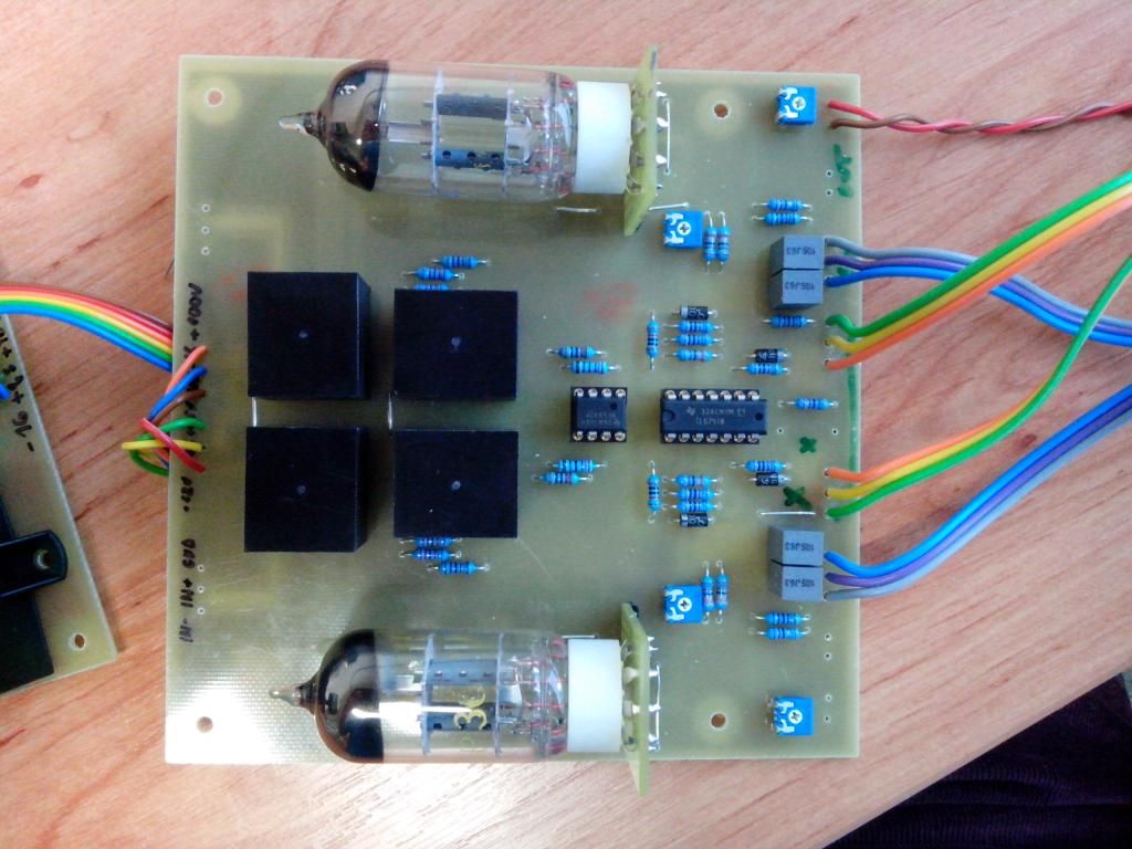
A while ago I decided to bring an old project of Kent Stevenson and PRR of a simple affordable DIY 12AU7 compressor unit back to life.
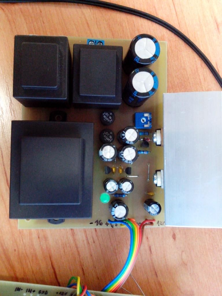
I gave the project a little update, using the components available in my country, updated the PCB a little bit, and did my own take on the power supply, which I designed from the basic components available in my local electronic parts store, no need for winding my own transformer. Which I can do but not in my current life situation
I am an electrotechnics and communications engineer, two years fresh off school. Audio has been a great passion of mine, since I also make and record music.
But please don't be too harsh on me, I am no expert in audio systems or measurements, and I know, I sometimes ask a dumb question...
So here goes...
First the pictures:
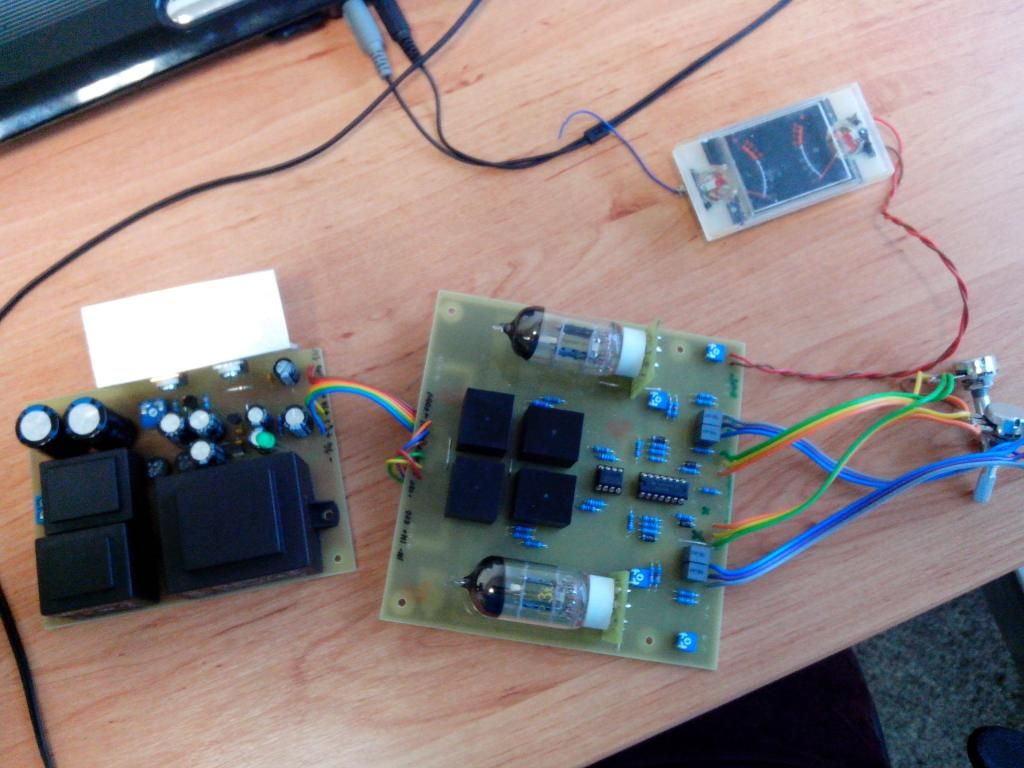
Second the description:
The compressor works, as far as I can tell. I can measure the output signal, the input is differential, but I feed it with a single ended signal generator.
What bugs me is HOW TO MEASURE A COMPRESSOR???
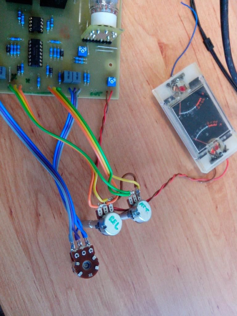
I can measure bandwidth of the unit, limited by the cheap transformers, but I don't see no (or very little) change when turning the potentiometers of ATTACK and RELEASE.
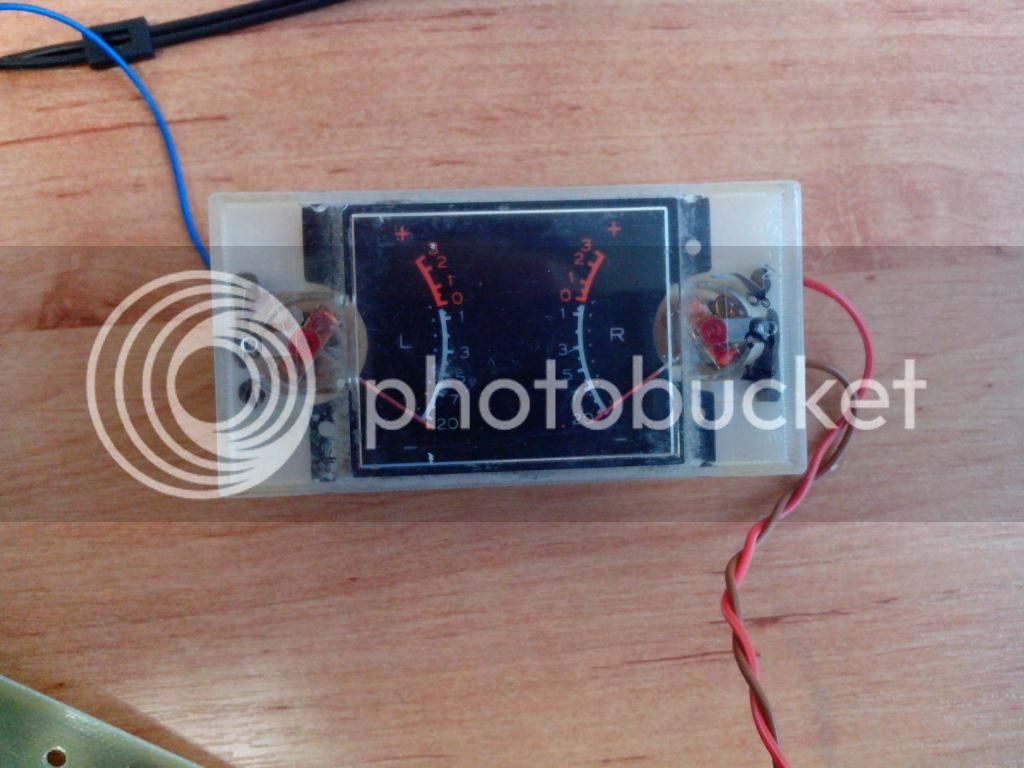
Another thing that bugs me is the VU meter (old VU from a vintage cassette recorder). I can't get no response from it, only when I turn the 100 Ohm trimmer the needle rises.
I measured the Ohmic resistance using DMM of the VU meter, which is 27,9 Ohm when connected in circuit and 634,3 Ohm unconnected.
Third is the info on the transformers, and all the materials I was able to get on this project, so that future generations can find it.
Transformers I used:
http://www.tme.eu/en/details/tr-1_1/pcb-transformers/
And last thing I want is to share the .brd and .sch files from Eagle 5, in exchange for the community help
A while ago I decided to bring an old project of Kent Stevenson and PRR of a simple affordable DIY 12AU7 compressor unit back to life.
I gave the project a little update, using the components available in my country, updated the PCB a little bit, and did my own take on the power supply, which I designed from the basic components available in my local electronic parts store, no need for winding my own transformer. Which I can do but not in my current life situation
I am an electrotechnics and communications engineer, two years fresh off school. Audio has been a great passion of mine, since I also make and record music.
But please don't be too harsh on me, I am no expert in audio systems or measurements, and I know, I sometimes ask a dumb question...
So here goes...
First the pictures:
Second the description:
The compressor works, as far as I can tell. I can measure the output signal, the input is differential, but I feed it with a single ended signal generator.
What bugs me is HOW TO MEASURE A COMPRESSOR???
I can measure bandwidth of the unit, limited by the cheap transformers, but I don't see no (or very little) change when turning the potentiometers of ATTACK and RELEASE.
Another thing that bugs me is the VU meter (old VU from a vintage cassette recorder). I can't get no response from it, only when I turn the 100 Ohm trimmer the needle rises.
I measured the Ohmic resistance using DMM of the VU meter, which is 27,9 Ohm when connected in circuit and 634,3 Ohm unconnected.
Third is the info on the transformers, and all the materials I was able to get on this project, so that future generations can find it.
Transformers I used:
http://www.tme.eu/en/details/tr-1_1/pcb-transformers/
And last thing I want is to share the .brd and .sch files from Eagle 5, in exchange for the community help


