You are using an out of date browser. It may not display this or other websites correctly.
You should upgrade or use an alternative browser.
You should upgrade or use an alternative browser.
U73b from scratch
- Thread starter DaveP
- Start date


Help Support GroupDIY Audio Forum:
This site may earn a commission from merchant affiliate
links, including eBay, Amazon, and others.

This is where we are today:-
Faceplate
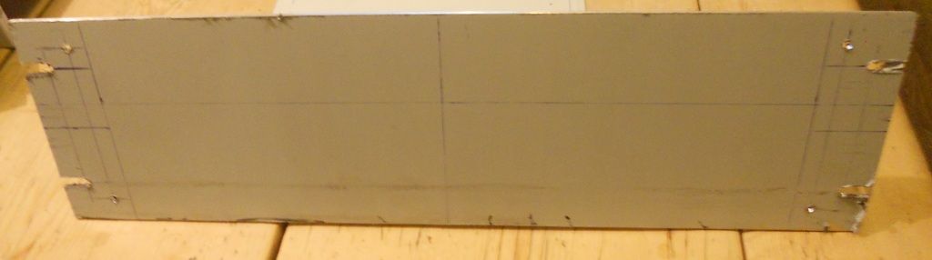
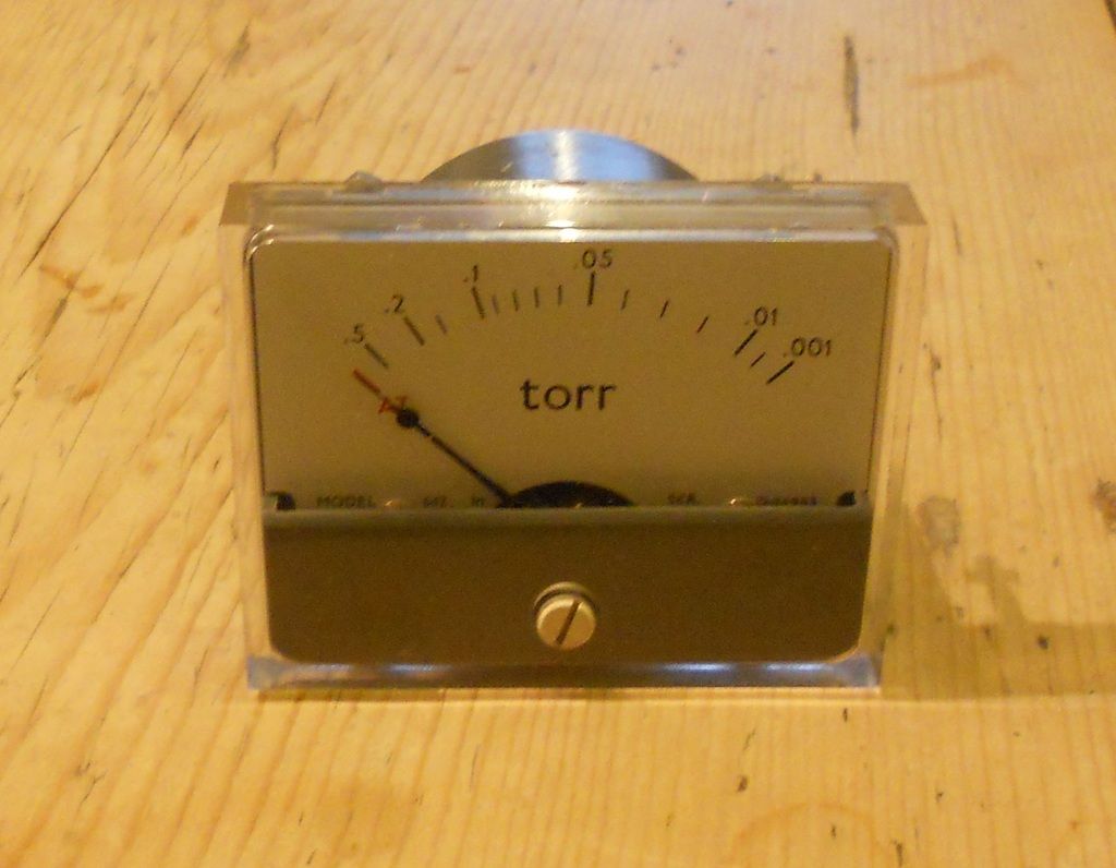
Original 1960's meter will have a new dB scale
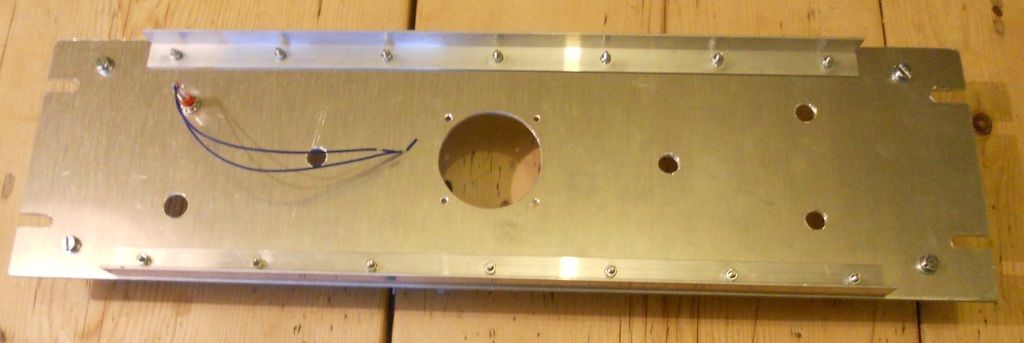
Chassis Parts cut to size. Don't worry, it will look better with the plastic off :-\
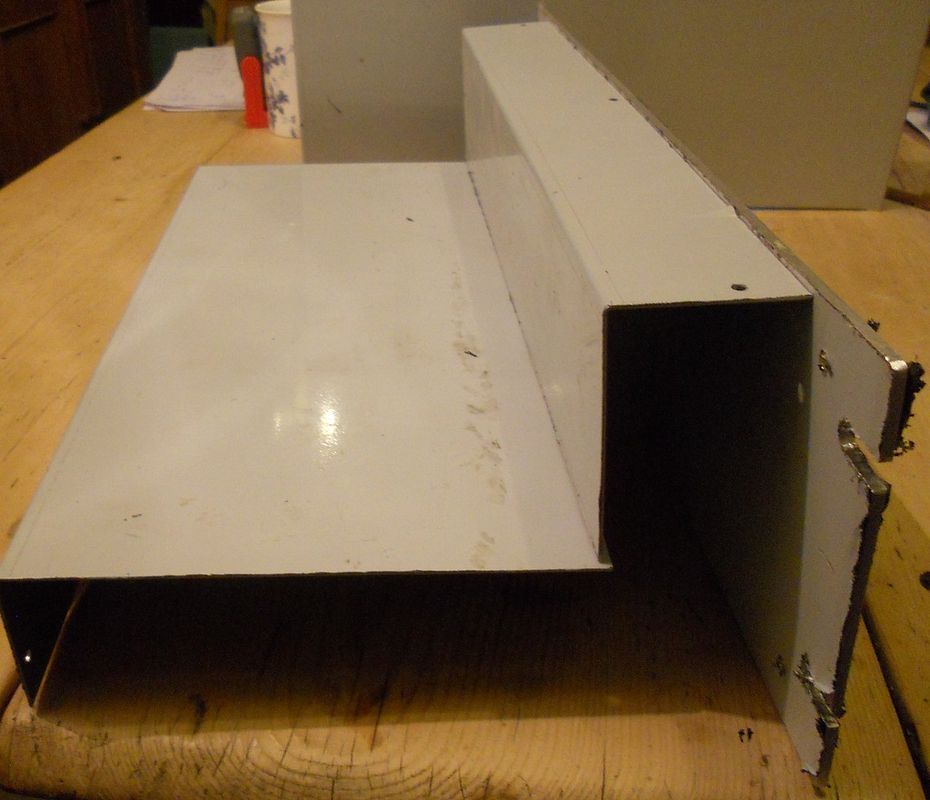
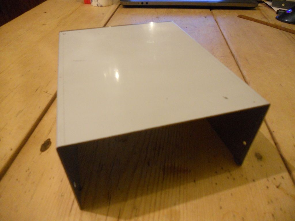
This will be cut to make the transformer cover.
That's it for tonight.
DaveP
Faceplate

Original 1960's meter will have a new dB scale

Chassis Parts cut to size. Don't worry, it will look better with the plastic off :-\

This will be cut to make the transformer cover.

That's it for tonight.
DaveP
This evenings instalment:-
I've been doing some working out with this lot
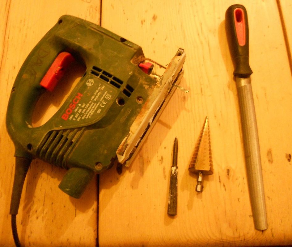
The cone drill is a dream to use and because its stepped you can stop and check the fit easily.
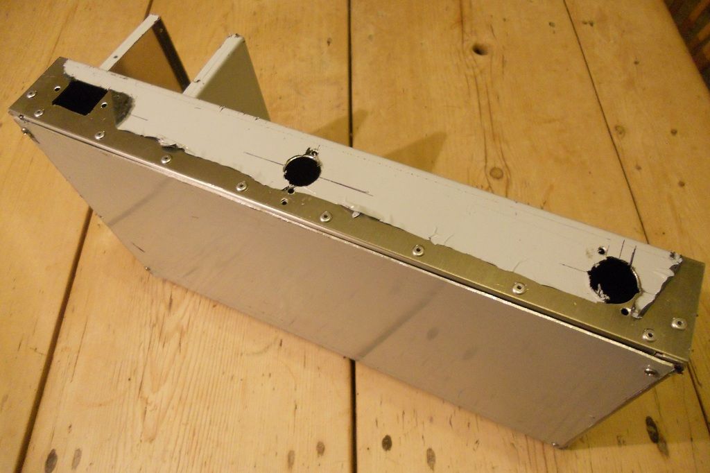
I've cut out the major holes on the back panel
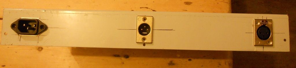
I've also made the removable base panel, but its not very photogenic. :")
Best
DaveP
I've been doing some working out with this lot

The cone drill is a dream to use and because its stepped you can stop and check the fit easily.
I've cut out the major holes on the back panel

I've also made the removable base panel, but its not very photogenic. :
Best
DaveP
I've got more to show from my labours tonight. I was able to start putting the chassis together.
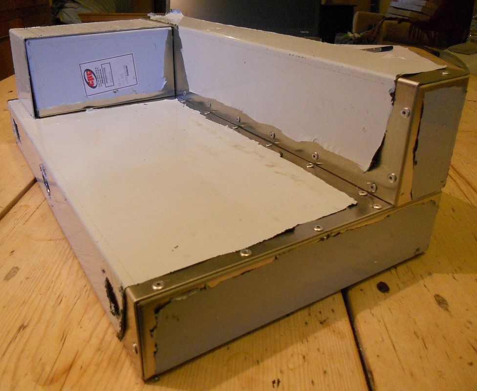
It's still under wraps to stop it getting scratched.
The faceplate will be removable and screwed to the front.
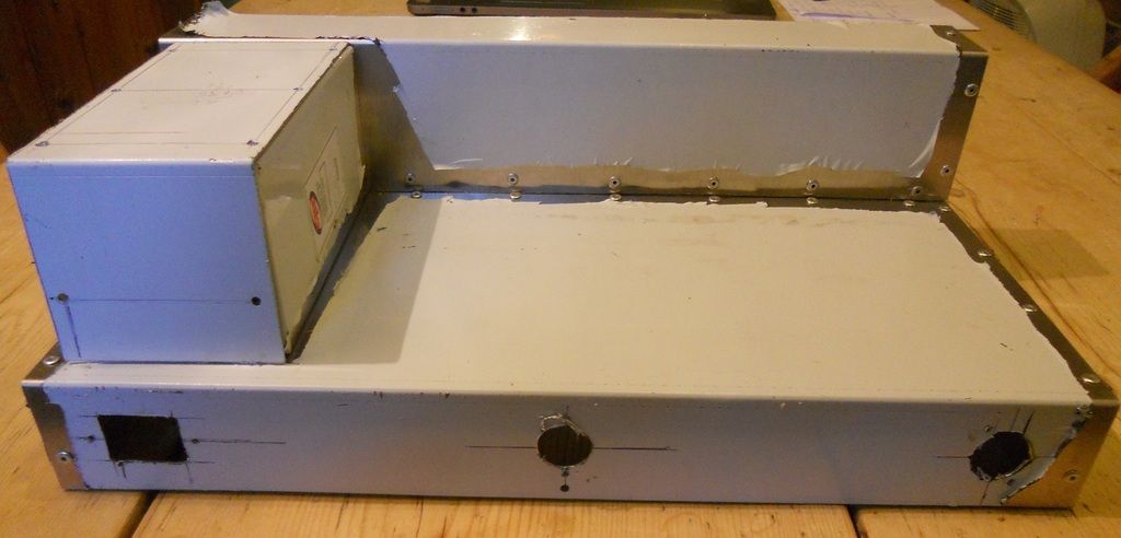
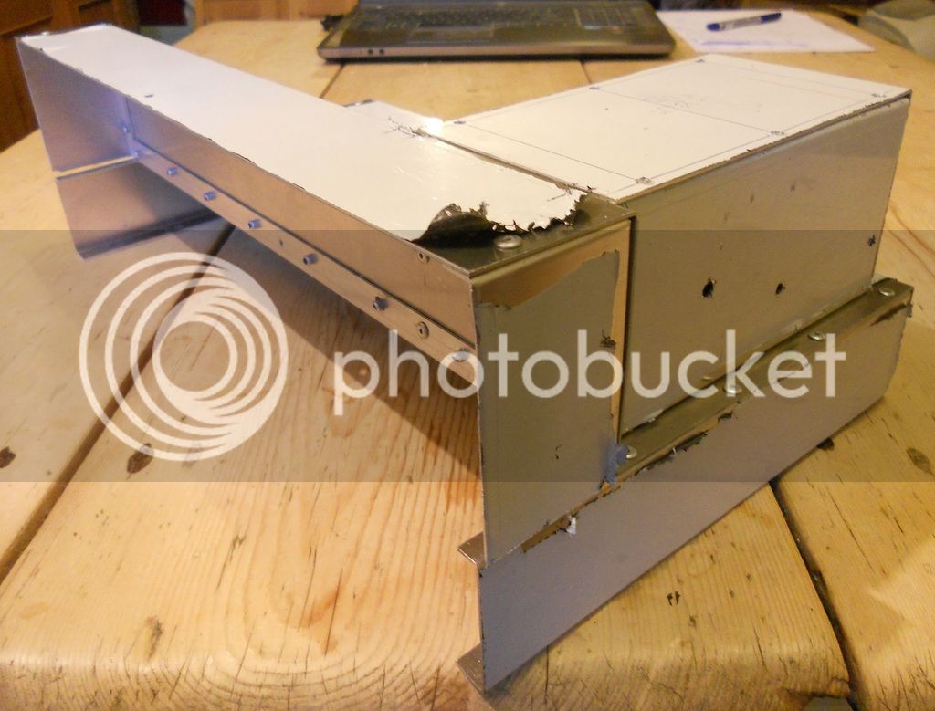
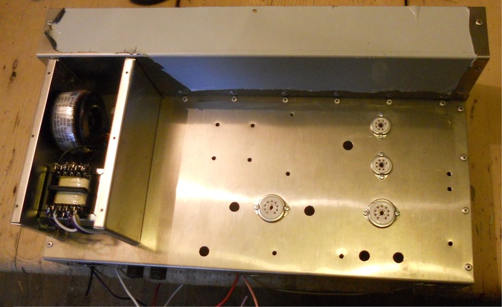
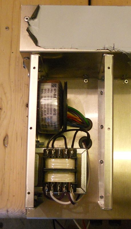
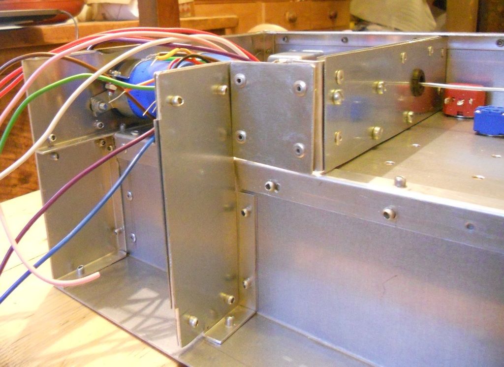
Back view with transformer box.
This is how the power transformers will fit.

The box will have some sandwiched shielding to the side to prevent hum radiation, also notice that the transformers are at right angles.
Best
DaveP

It's still under wraps to stop it getting scratched.

The faceplate will be removable and screwed to the front.

Back view with transformer box.
This is how the power transformers will fit.

The box will have some sandwiched shielding to the side to prevent hum radiation, also notice that the transformers are at right angles.
Best
DaveP
ruairioflaherty
Well-known member
Enjoying this!
holly molly Dave! Another classic build in the making...
I am amazed!
I am amazed!
I am just using the knowledge that was given to me at school.
I was probably the only one who was listening during metalwork, woodwork and technical drawing classes. They were all subjects in their own right back in the early 60's, not like today with them all lumped into one like CDT, whatever that means. The skills I learned back then have probably been more use to me than anything else! Oh that I could have taken in the Maths as easily
Before you get too impressed, I don't own a smart phone and I can't text, I do have a mobile phone to make phone calls though, now how weird is that?
I have done more on the amp tonight, but its not worthy of a pic.
best
DaveP
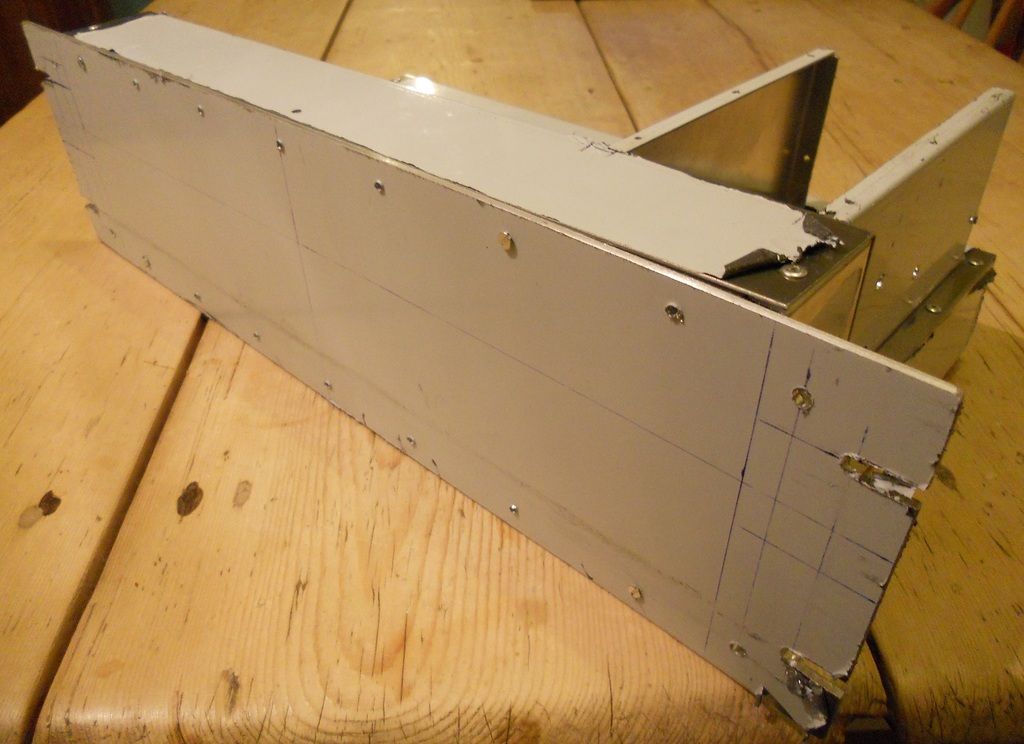
Here is where we are now, the basic chassis is almost finished.
I've used aluminium angle to attach the front panel to the main chassis. This will be removable with self-tapping screws.
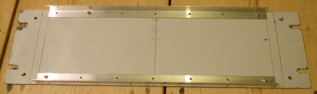
I will have to countersink all the screw heads on the front which takes some time. :-\
The base is now finished.
This is how it will look with the front panel attached.
 .
.
When the above chores are done, I can start fitting the major components and valve bases. I have decided to keep it original and use the E88CC. Even though I lose output by not using a choke (almost half), The loss is made up by using a 15K:600 OPT.
Best
DaveP
I've used aluminium angle to attach the front panel to the main chassis. This will be removable with self-tapping screws.

I will have to countersink all the screw heads on the front which takes some time. :-\
The base is now finished.

This is how it will look with the front panel attached.
 .
.When the above chores are done, I can start fitting the major components and valve bases. I have decided to keep it original and use the E88CC. Even though I lose output by not using a choke (almost half), The loss is made up by using a 15K:600 OPT.
Best
DaveP
I've been working on the new meter scale, it's very time consuming.
I found the German DIN Font from the period and re-scaled the meter face after scanning it in.
Windows Paint is very good and just about at my level.
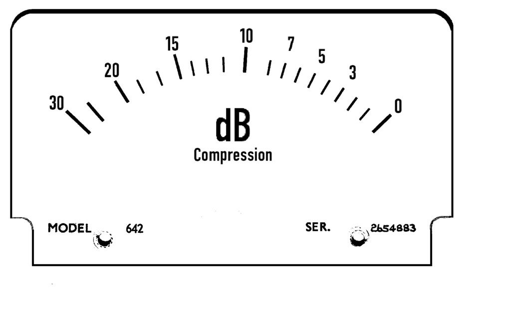
I've still got a bit of cleaning up to do, but that's basically it.
I hope you think it looks the part, because the original U73b did not have a meter!
best
DaveP
Hello Dave!
Awesome!
I am interested in the name of the font if you have it...
Cheers
thomas
Awesome!
I am interested in the name of the font if you have it...
Cheers
thomas
Hi Thomas,
The one I'm using is DIN Schriften Engschrift. Also called DIN 1451, this typeface was developed by the Deutsches Institut für Normung (the German Institute for Standardisation), and is used for road and railway signs in Germany and other countries.
There are several of these that you can check out at this site:-
http://www.identifont.com/about.html
This is really useful as it takes you through an elimination procedure to find the font you are trying to identify.
Best
DaveP
Wraps off the front panel.
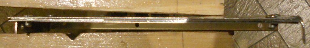
This is the back of it showing the angle section which joins it to the main chassis.
Front view with a few parts laid on to get an idea of the finished look.
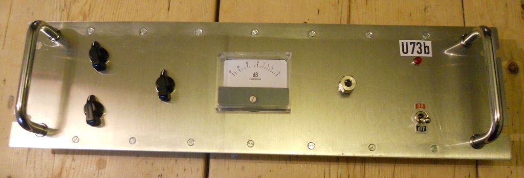
The switches on the left are the in/out switch, the release timing and the Limit/Compressor switch. The meter has a zero pot on the right. All the fixing screws had to be carefully countersunk, very tedious but worth it.
Best
DaveP
This is the back of it showing the angle section which joins it to the main chassis.

Front view with a few parts laid on to get an idea of the finished look.

The switches on the left are the in/out switch, the release timing and the Limit/Compressor switch. The meter has a zero pot on the right. All the fixing screws had to be carefully countersunk, very tedious but worth it.
Best
DaveP
Thanks for the font! Can't wait to see more...!
I've been working on the layout for days now :-[
Always best to sleep on it then look at it again next morning, amazing how you can see mistakes that should have been obvious, the power of the sub-concious at work I guess.
But after many different layouts, I've come up with this:-
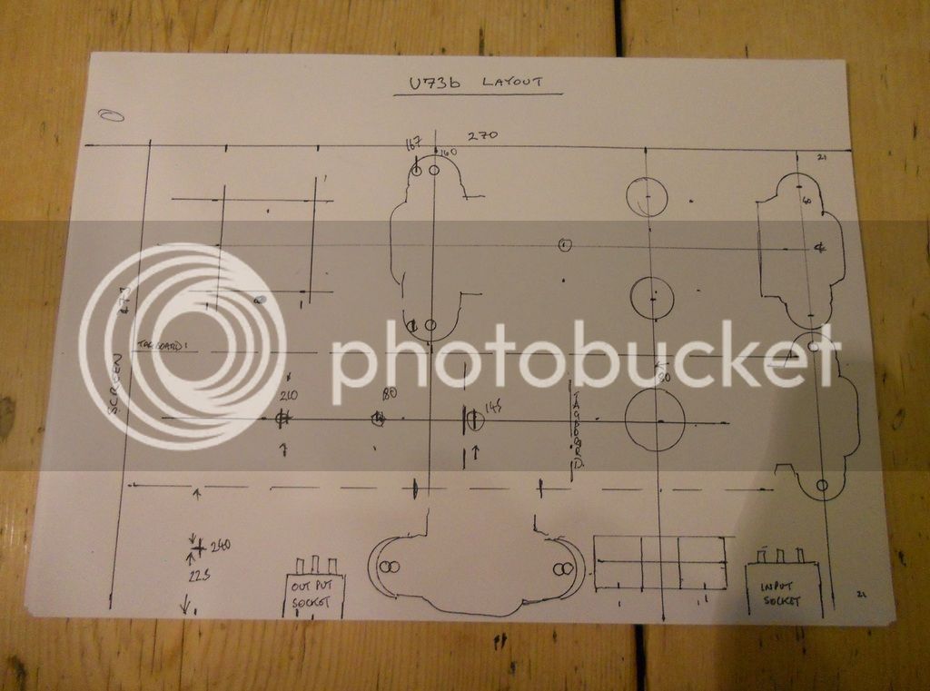
I am going with this one and if it throws up any snags, I will just have to find a workaround, that's what prototypes are all about.
I had to make a slight change to this when I started marking up the chassis because there were seams underneath that were best avoided. But it's very close to the paper design.
Most of these components will be inside and upside down ??? There are internal screens to be fitted, so I had to finish the layout so they can have the right holes drilled in them to accommodate the busbar.
The power supply is similar to others I've done, so it doesn't need much extra design work. I'll be cutting all the holes next, so that will be the next post.
best
DaveP
Always best to sleep on it then look at it again next morning, amazing how you can see mistakes that should have been obvious, the power of the sub-concious at work I guess.
But after many different layouts, I've come up with this:-

I am going with this one and if it throws up any snags, I will just have to find a workaround, that's what prototypes are all about.
I had to make a slight change to this when I started marking up the chassis because there were seams underneath that were best avoided. But it's very close to the paper design.

Most of these components will be inside and upside down ??? There are internal screens to be fitted, so I had to finish the layout so they can have the right holes drilled in them to accommodate the busbar.
The power supply is similar to others I've done, so it doesn't need much extra design work. I'll be cutting all the holes next, so that will be the next post.
best
DaveP
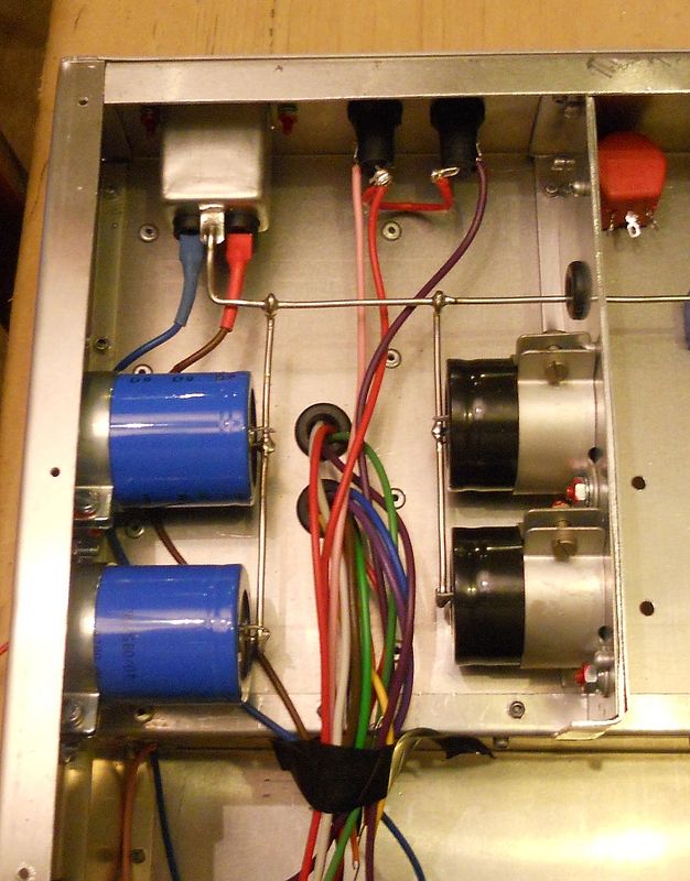
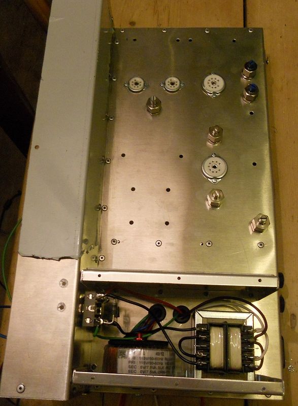
Most of the holes have now been drilled for the major components and I've fitted the valve bases, fuses and power transformers wired for 115V.
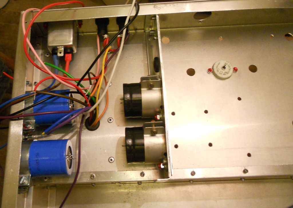
This is the view from underneath
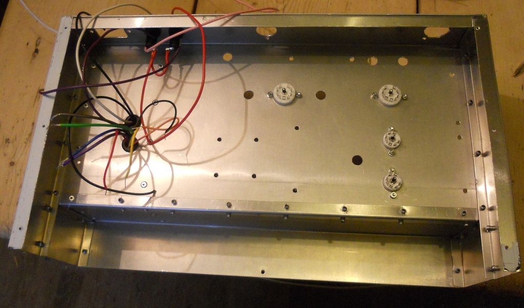
Lots of wires to sort out
Where I can, I pre-wire components before fitting, its a lot less hassle. The earth terminal has been drilled out to take the earth busbar. I always use a basic filtered socket in case of mains borne interference.
I use one of the wife's old hair-dryers for the shrink -fit, have to cover the inlet a little to get it hot enough!
The power supply is provided by two transformers, that way I can tailor the supply to the correct currents.
The input and output wires come through the two grommets and will go to a tag strip in due course. The toroid wires are as close to the chassis as possible as they are like a magnetic field hernia and I don't want anything spraying over the rest of the amp. I am fitting some steel shields over the power supply later on.
best
DaveP

This is the view from underneath

Lots of wires to sort out
Where I can, I pre-wire components before fitting, its a lot less hassle. The earth terminal has been drilled out to take the earth busbar. I always use a basic filtered socket in case of mains borne interference.

I use one of the wife's old hair-dryers for the shrink -fit, have to cover the inlet a little to get it hot enough!
The power supply is provided by two transformers, that way I can tailor the supply to the correct currents.

The input and output wires come through the two grommets and will go to a tag strip in due course. The toroid wires are as close to the chassis as possible as they are like a magnetic field hernia and I don't want anything spraying over the rest of the amp. I am fitting some steel shields over the power supply later on.
best
DaveP
Not much to show for tonight's efforts, I made the three layered screen.
This consists of an aluminium layer sandwiched between two galvanised steel sheets. From the tests I did earlier on, I found that layers are quite effective as the magnetic flux does not like changing mediums very much.
This screen is useful for attaching capacitors.
There are two 47,000uF 16V caps for the 6.3V DC supply and two 470uF 450V caps for the HT. There is no subtlety in this, they just crush the hum down to uV levels. If this comp hums, it will be down to my crappy layout and not an inadequate power supply.
Best
DaveP

This consists of an aluminium layer sandwiched between two galvanised steel sheets. From the tests I did earlier on, I found that layers are quite effective as the magnetic flux does not like changing mediums very much.
This screen is useful for attaching capacitors.

There are two 47,000uF 16V caps for the 6.3V DC supply and two 470uF 450V caps for the HT. There is no subtlety in this, they just crush the hum down to uV levels. If this comp hums, it will be down to my crappy layout and not an inadequate power supply.
Best
DaveP
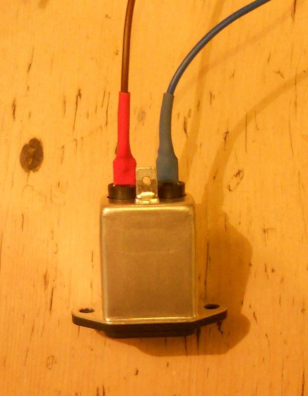
I've been working on the rectifiers and encountered an unexpected problem. After moving to France, I have been unable to find my supply of silicone heat sink insulators. No problem, I'll just order some more, but after fruitless searching of RS and Farnell websites I realised that they no longer sell them, fortunately I was able to order from a supplier on Amazon. I guess they don't expect people to work with discrete components any more.
Took a long time to drill and tap threads into this heatsink.
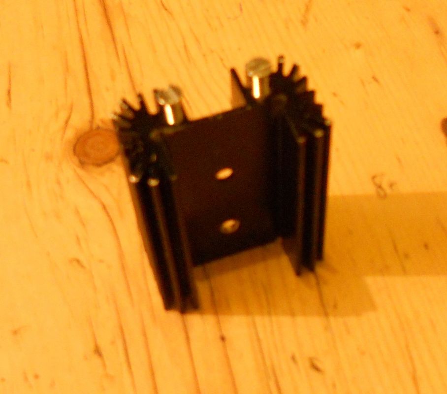
This is for the schottky diode package for the heater supply. TO220 format and needs a the silicone insulating pad as its screwed to the chassis.
Handy tip for making a custom bridge rectifier, screw the tags to some wood while you solder.
Sorry for blurred pic, but you get the idea.
Finished article
I've used UF5408's for two reasons, one they are fast so low capacitance and less hash, two they can easily handle the surge into the 470uF HT caps, 1N4007's are on the limit.
This is the bridge in place
I have also added two steel screens, one either side to make a sandwich, on the transformer box amp side.
This took quite a long time to make, but its done and dusted now. The two countersunk holes top right are where the heat sink attaches.
best
DaveP
Took a long time to drill and tap threads into this heatsink.

This is for the schottky diode package for the heater supply. TO220 format and needs a the silicone insulating pad as its screwed to the chassis.
Handy tip for making a custom bridge rectifier, screw the tags to some wood while you solder.

Sorry for blurred pic, but you get the idea.
Finished article

I've used UF5408's for two reasons, one they are fast so low capacitance and less hash, two they can easily handle the surge into the 470uF HT caps, 1N4007's are on the limit.
This is the bridge in place

I have also added two steel screens, one either side to make a sandwich, on the transformer box amp side.

This took quite a long time to make, but its done and dusted now. The two countersunk holes top right are where the heat sink attaches.
best
DaveP
Thanks to everyone for the likes, I must be doing something right here ;D
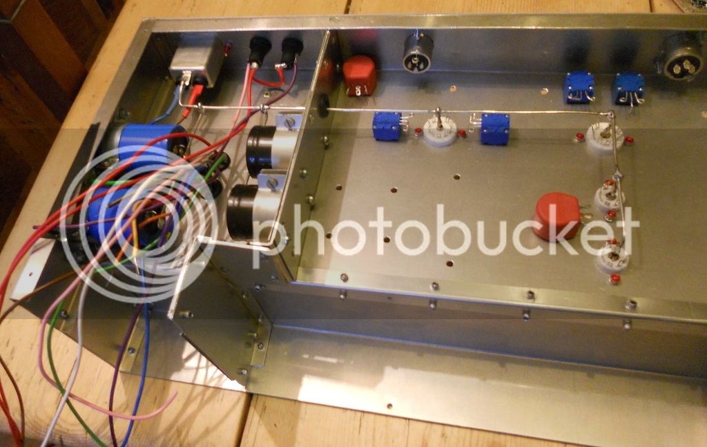
The busbar went in this evening and all the pots.

14swg tinned copper, needs a 40W iron to solder that much metal.
All the power supply caps earthed easily.
This is the view topside.
The pot clamps are not cheap but it makes it a quality job. The pots are required for the initial setting up (see my translation), then they are left undisturbed.
Best
DaveP
The busbar went in this evening and all the pots.

14swg tinned copper, needs a 40W iron to solder that much metal.

All the power supply caps earthed easily.
This is the view topside.

The pot clamps are not cheap but it makes it a quality job. The pots are required for the initial setting up (see my translation), then they are left undisturbed.
Best
DaveP
Zander I'm doing my best, but sometimes the wife has other ideas of what I should be doing :-X
Anyway, I have made the final screen to protect the circuits on the front panel from ac power.
Again this is a steel sandwich.
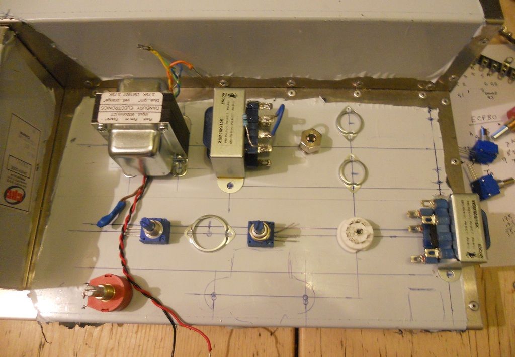
I have made a very rough mock-up of this amp to test various Edcor transformers, and the best results have been with the WSM15k:15k as the IPT This has a nice flat frequency response. In fact all the WSM 15k types are flat, strange that other types are not, its worth checking out Edcor's site for these.
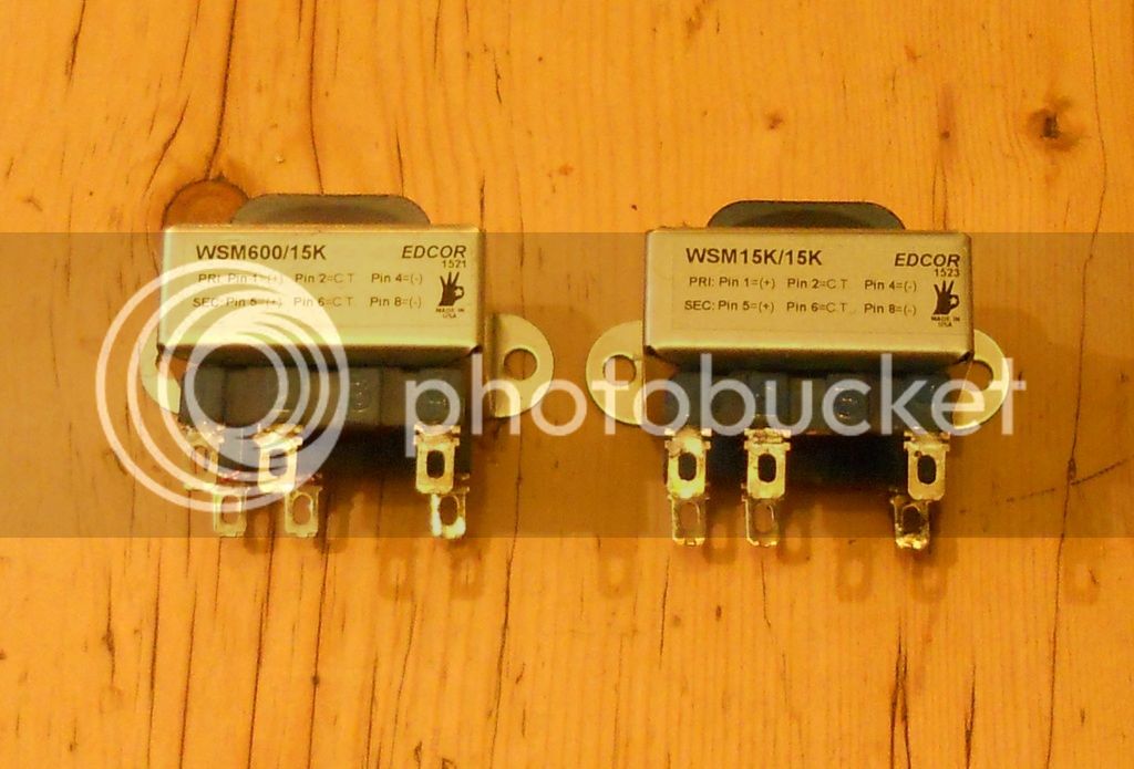
These are the transformers I shall be using to replace the original IPT. I won't try splitting the CT on the 15k:15k as I have found another way to get the separate signal to the sidechain amp
The pads isolate the transformers and the extra transformer is a 15k:600 which helps with the required voltage reduction to the ECF80, the one in the picture is a 600:15k but it works in reverse too.
I have some metal clad power resistors on order for the heater DC supply and getting the tubes working on DC will be the next stage before the components start going in.
best
DaveP
Anyway, I have made the final screen to protect the circuits on the front panel from ac power.

Again this is a steel sandwich.

I have made a very rough mock-up of this amp to test various Edcor transformers, and the best results have been with the WSM15k:15k as the IPT This has a nice flat frequency response. In fact all the WSM 15k types are flat, strange that other types are not, its worth checking out Edcor's site for these.

These are the transformers I shall be using to replace the original IPT. I won't try splitting the CT on the 15k:15k as I have found another way to get the separate signal to the sidechain amp

The pads isolate the transformers and the extra transformer is a 15k:600 which helps with the required voltage reduction to the ECF80, the one in the picture is a 600:15k but it works in reverse too.
I have some metal clad power resistors on order for the heater DC supply and getting the tubes working on DC will be the next stage before the components start going in.
best
DaveP
Similar threads
- Replies
- 73
- Views
- 3K