You are using an out of date browser. It may not display this or other websites correctly.
You should upgrade or use an alternative browser.
You should upgrade or use an alternative browser.
muso saver
- Thread starter JohnRoberts
- Start date


Help Support GroupDIY Audio Forum:
This site may earn a commission from merchant affiliate
links, including eBay, Amazon, and others.

jasonallenh
Well-known member
I want one of these, kit, assembled, whatever... Regardless of UL listing. Not sure what good that would do anyway, considering the standard (UL listed) commercial tester does not work.
The UL listing has almost nothing to do with product function. mainly that it will not catch fire of harm the operator.jasonallenh said:I want one of these, kit, assembled, whatever... Regardless of UL listing. Not sure what good that would do anyway, considering the standard (UL listed) commercial tester does not work.
It is interesting that the UL spec for the commercial tester insists on fine print caveats for the instruction sheet that list the several things it can't test.. They don't specifically mention RPBG wiring, but say the commercial tester can't identify multiple faults present at the same time.
I need to perform a few more tests before I am ready to submit it to UL. They specify a 100M ohm insulation resistance tested at 500V. Of course the spec does not anticipate a touch probe, but I have my circuit working with 100M resistor in series with the touch probe.
I may have to pay them extra to get them to accommodate my extra capability, if it requires amending the UL spec. .
JR
After investing a bunch of time and money (more time than money) into this project I am losing interest. I'm too old to start yet another business (charity). :-(
I am at the stage where I would need to pay UL $10k+ just to start a file, and my unconventional approach would probably add test expenses on top of that.
I am ready to abandon making and selling these myself. Also I have been unsuccessful developing a constructive partnership with an existing tester manufacturer. As promised I am publishing the technology so any and all can use it for free. I never did this for money.
http://www.johnhroberts.com/OD1.htm
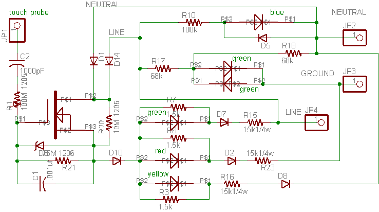
I have published a written description of how this works (at link above). I invite any circuit knowledgeable guys out there to check this out and tell me if there are still parts of the circuit that are not clear. Most of this is obvious but some is pretty obscure, especially how the local reference actually works.. I didn't figure it out for several months into the development. There is a difference between making something that works, and understanding how it works. :-\ BTW there are no unnecessary parts, every component in the schematic is doing something useful.
Please share this with anyone who might have interest. I expect the technology has multiple human safety applications beyond outlet testers.
JR
PS: This new OD-1 web page is a work in process and I will add more information like a comprehensive BOM, etc
[edit in response to complaint I received telepathicly from a forum member I tweaked the schematic, and added a parts list to my web page. All the diodes and one mosfet are 400V parts. /edit]
I am at the stage where I would need to pay UL $10k+ just to start a file, and my unconventional approach would probably add test expenses on top of that.
I am ready to abandon making and selling these myself. Also I have been unsuccessful developing a constructive partnership with an existing tester manufacturer. As promised I am publishing the technology so any and all can use it for free. I never did this for money.
http://www.johnhroberts.com/OD1.htm
I have published a written description of how this works (at link above). I invite any circuit knowledgeable guys out there to check this out and tell me if there are still parts of the circuit that are not clear. Most of this is obvious but some is pretty obscure, especially how the local reference actually works.. I didn't figure it out for several months into the development. There is a difference between making something that works, and understanding how it works. :-\ BTW there are no unnecessary parts, every component in the schematic is doing something useful.
Please share this with anyone who might have interest. I expect the technology has multiple human safety applications beyond outlet testers.
JR
PS: This new OD-1 web page is a work in process and I will add more information like a comprehensive BOM, etc
[edit in response to complaint I received telepathicly from a forum member I tweaked the schematic, and added a parts list to my web page. All the diodes and one mosfet are 400V parts. /edit]
Audio1Man
Well-known member
Hi John
I think that your tester is very elegant. I do think that it may need another feature. Not all user (consumers) read and will understand the LED matrix. You may consider adding a FLASHING ERROR INDICATOR or ? for non teckies.
Great design Duke")
I think that your tester is very elegant. I do think that it may need another feature. Not all user (consumers) read and will understand the LED matrix. You may consider adding a FLASHING ERROR INDICATOR or ? for non teckies.
Great design Duke
The cheap 3 lamp tester requires a look up table to interpret the results. Mine keeps it simple,,, Green is always good (line is hot as it should be), red is always bad (ground is hot and can kill you), and yellow is caution but won't kill you (neutral hot wrong but still safe in most gear). If you forget that legend and the screening has worn off the tester, just think about what you do if you come to stop light. If it's green you are Ok to go, if red not OK and you stop.Audio1Man said:Hi John
I think that your tester is very elegant. I do think that it may need another feature. Not all user (consumers) read and will understand the LED matrix. You may consider adding a FLASHING ERROR INDICATOR or ? for non teckies.
Great design Duke
I could add a blink feature and even considered an audible annunciator for hot ground hazards but the PCB is a pretty tight fit already. A secondary consideration is to keep the current low enough that it doesn't trip a GFCI if one of those is mis-wired. UL also stipulated how much current can flow into ground (3 mA).
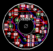
It really started to get a little crowded when I had to use larger SMT passive components to handle the 500V insulation resistance test. Small SMD components get weird at high voltages. One small 100M smd resistor only delivered 40-60M of resistance at 500V.
This project was a learning experience while I'm not sure I needed to learn all of this. 8)
JR
Audio1Man
Well-known member
Hi John
The 0805 parts are rated typ 350 volts. I use two in series and keep the voltage below 250 volt each. Routed PCB or holes do help.
Microphone and switching PS have similar problem with leakage. Your learning process will always help you.
Duke
The 0805 parts are rated typ 350 volts. I use two in series and keep the voltage below 250 volt each. Routed PCB or holes do help.
Microphone and switching PS have similar problem with leakage. Your learning process will always help you.
Duke
Yup I considered putting lower voltage parts in series. Logically the breakdown mode from high voltage should force them to share equally not to mention the inherent resistive voltage divider so it "should work". In fact I may have done some measurements at 500V that confirmed it works. I also considered using a much larger part (1W) as a cheaper way to get the rated voltage, but as I ran out of PCB real estate I abandoned the even larger or even more components approach. I could realize the 500V I needed with single 1206 parts...Audio1Man said:Hi John
The 0805 parts are rated typ 350 volts. I use two in series and keep the voltage below 250 volt each. Routed PCB or holes do help.
Microphone and switching PS have similar problem with leakage. Your learning process will always help you.
Duke
JR
AusTex64
Well-known member
- Joined
- Jun 3, 2013
- Messages
- 525
[/quote] I've never seen bootleg grounds here. Nobody in his right mind would do that. I was horrified when I learnt it was common practice in Denmark.
[/quote]
I had an electrician do it when wiring a 30A service to my floating boat dock! I would agree many so called "electricians" are not in their right minds. I ended up giving him quite a lecture/ass chewing over it.
[/quote]
I had an electrician do it when wiring a 30A service to my floating boat dock! I would agree many so called "electricians" are not in their right minds. I ended up giving him quite a lecture/ass chewing over it.
I didn't get it at a glance. When PMed, JR said I should post on forum. I generally agree, but then my parents came to visit.
In (many) idle moments I hacked-up my understanding in "readable" form.

Power arrives at the left. Power pins marked in order of (nominal) hotness: Line, Neutral, Ground. Functions laid left to right. Details like resistors and bi-di diodes mostly abstracted out. The highly unusual "Touch" contact called-out and illustrated as in use, with ambient electric field swirling around the user. Cleverness in buffer ignored.
In (many) idle moments I hacked-up my understanding in "readable" form.
Power arrives at the left. Power pins marked in order of (nominal) hotness: Line, Neutral, Ground. Functions laid left to right. Details like resistors and bi-di diodes mostly abstracted out. The highly unusual "Touch" contact called-out and illustrated as in use, with ambient electric field swirling around the user. Cleverness in buffer ignored.
Attachments

Thanks for the visual schematic.
The left side with all the sundry display indications is pretty straightforward.
The difficult part to explain is the buffer. In a perhaps oversimplified explanation when that pretty girl is "not" touching the input contact, the output of the buffer is high impedance and free to swing anywhere so none of the 3 indicator LEDs light up even if energized.
When the pretty girl touches the probe, the buffer turns on and provides a low impedance "ground" reference (and I use that term loosely) to the three indicator LEDs. For a properly wired outlet only the green Line LED is energized so it lights up green for good. If the line and neutral are reversed, the yellow LED is energized and lights up. If ground is hot the red LED lights up.
I'd love to explain the electrical model of the human body touching the probe (but I'd have to understand it better). It isn't simple, and isn't even what i though it was when I started designing this circuit some time ago. My best guess is that the body is like a decent sized capacitor plate (antenna?) with internal distributed resistance and capacitance. For normal environments the human body is sitting at roughly 0V DC and 0V AC wrt the environment. The human body's tens of PF is enough capacitance to hold on the buffer during negative swings, however if the body is energized by some other voltage source, that non-zero state voltage can corrupt reading accuracy, so another part of the human body model that is important is the environment it is connected to.
Leakage from an LED lamp fixture attached to my metal work shelf above my work bench can cause erroneous readings, if i accidentally brush up against the metal shelf while touching the probe, with the LED lamp fixture turned on.
AFAIK I am the only tester who experienced environment related errors, I've had a few beta units out in the field with good results.
JR
> For normal environments the human body is sitting at roughly 0V DC and 0V AC wrt the environment.
That's what I'm unsure of.
If we are on a dirt-slab, literal "earth" dominates the field almost everywhere.
If we are on a tall dry tower with knob-and-tube open 120V wiring, we may suspect an average 60V field. And I had suspected that a "normally wired room" might approach this point.
In my dining room I just tried a Fluke DMM, black to electric ground, red in my hand. Generally about 300mV AC. Down to 20mV if my finger brushes one side of an all-plastic 2-pin plug, 300mV other side.
So in ultra limited testing, the floating (rubber shoes on carpet on wood floor) body is "0V AC reference" for safety purposes. Part-volts are not dangerous.
I will not grant the "0V DC" in winter. We know full well (places with dry heat) that we can build spark-size static electric fields on our bodies. I don't think this is a primary safety issue on stage.
In my early thinking I was looking for a DC path to some earth ground to buffer, but we are surrounded by insulators and very slight conductors and fields, AC or DC (static). I have come to the mindset that my buffer doesn't work that way...PRR said:> For normal environments the human body is sitting at roughly 0V DC and 0V AC wrt the environment.
That's what I'm unsure of.
If we are on a dirt-slab, literal "earth" dominates the field almost everywhere.
If we are on a tall dry tower with knob-and-tube open 120V wiring, we may suspect an average 60V field. And I had suspected that a "normally wired room" might approach this point.
In my dining room I just tried a Fluke DMM, black to electric ground, red in my hand. Generally about 300mV AC. Down to 20mV if my finger brushes one side of an all-plastic 2-pin plug, 300mV other side.
So in ultra limited testing, the floating (rubber shoes on carpet on wood floor) body is "0V AC reference" for safety purposes. Part-volts are not dangerous.
I will not grant the "0V DC" in winter. We know full well (places with dry heat) that we can build spark-size static electric fields on our bodies. I don't think this is a primary safety issue on stage.
The outlet mains power connections; Line, Neutral, and Ground (if present)... are low impedances to voltages that are definitely referenced to utility 0V.
When nobody it touching the input reference probe, the MOSFET is cut off, and during the negative mains power swing it swings down to a major fraction of mains power negative voltage. During the positive half swing the indicator LEDs connected to utility 0V conduct and clamp the positive swing close but not that close to utility 0V.
BUT if a human is touching the input probe (gate) during the negative half cycle, a voltage divider is formed between that human's finger and MOSFET source with enough voltage drop to turn on the MOSFET. The drain draws current from the near utility 0V coming from neutral or ground, and delivers that current through the source to the energized indicator LED.
In early design attempts the LEDs would momentarily flash then go dark... It turns out the MOSFET gate drive would discharge the human capacitor to a negative DC voltage , just like a static charge charges up our human capacitor. Once the human is discharged to -160V or so no more indication.
My fix for that is a 10M pull up resistor (R20) that effectively recharges this human sawtooth generator every positive half cycle. As soon as I figured that out, I learned I could cap couple the input, for even more isolation.
It turns out the real 0V reference is the utility mains 0V , and the human is just supplying a tiny stray capacitance to some vague local ground to turn on the MOSFET during negative half cycles. I did some bench work to see how small this cap could be and it was pretty small but my estimate is that it is ultimately a stray C to utility ground. (Note My house has ungrounded outlets so maybe the stray C is to utility neutral). While it only needs to be maybe 10s of PF I made the input cap much larger to be insignificant compared to the stray C doing the magic.
I don't know if this helps but is my best guess, and agrees with my empirical bench experiments.
JR
> looking for a DC path to some earth
As you found: you can't have that. We all wear Keds or Sketchers, on plastic or wood floors. DC conductivity may be low (barefoot on concrete), but may be super high.
> 10M pull up resistor (R20) that effectively recharges this human sawtooth generator every positive half cycle.
I would just say it is "AC coupled" (with body cap as coupling cap). The sawtooth is familiar if you ever cap-coupled a grid and forgot the grid resistor, then really looked at the over-driven action.
> the human is just supplying a tiny stray capacitance to some vague local ground
"human body capacitance to a far ground is 100-200 pF"
www.extremeelectronics.co.uk/capacitance-of-a-human-body/
"capacitance of the person (typically between 180 — 200 pF)."
http://sciencedemonstrations.fas.harvard.edu/presentations/capacitance-human-body
"If we assume a perfectly spherical and conductive human body, we need approximately 30 pC to raise the voltage by 1 V, that would be 30 pF."
http://physics.stackexchange.com/questions/79912/how-capacitive-is-the-human-body
"....130pF to 210pF..."
http://home.mit.bme.hu/~kollar/IMEKO-procfiles-for-web/tc4/TC4-15th-Iasi-2007/Final_Papers/F191.pdf
"a body standing on a ground plane is calculated by means of the surface charge method. The human body consists of polyhedra in the calculation. In this paper, three types of polyhedra, with 765, 917, and 1529 surfaces, are used. It is found that the capacitance increases as the backs of the soles of the shoes approach the ground plane, that the body capacitance at the same height (10 mm) as the soles of the shoes is 120 to 130 pF, and that it is about 60 pF if the location of the soles is sufficiently high."
http://onlinelibrary.wiley.com/doi/10.1002/ecja.10025/abstract
"human body capacitance (HBC) is traditionally chosen as 100 pF. However, a simple geometric model seems to suggest considerably higher values. A series of experiments,.., gave values in the order of 100-150 pF when the capacitance was determined by an AC-bridge measurement, but 200-400 pF when the traditional static charge-sharing method was used. Further..."
http://orbit.dtu.dk/files/4363898/Jonassen.pdf
Somewhat lower pF numbers for much higher (non-power) frequencies.
A sudden thought: the fact that people play Theremins suggests there is no large 60Hz component to the electric field in a room (or stage) with power around. Else there would be a strong 60Hz FM on the tone, Yes, perhaps the traditional vibrato is in part to mask this.
Yup I think I've mentioned in passing the typical 100pF body capacitance (while surely varies with different size people), IIRC in series with 150 ohms, of course the key question is wrt what? Where do you connect the other VOM lead?
My probe input C is large wrt body C and my input R is crazy large wrt body R.
My gut sense is that the working condition presented to my probe that turns on the MOSFET is a couple ten pF to ground/neutral. If those pF couple to Line voltage the MOSFET stays cut off and no indications light. I can imagine a grossly mis-wired facility with large energized by line voltage ground panels that might trick my probe but that seems pretty low probability.
My anecdote of the leaky LED light fixture interfering with measurements is a 2 wire plug light fixture plugged into a reversed polarity outlet so what the light fixture thinks is neutral is actually line and couples that into my metal shelf.
I didn't experience any such weirdness in a number of different buildings I checked out.
JR
It is not very common but happens. Within the last year a cable technician was sent to the hospital while installing a cable box that was plugged into a RPBG mis-wired outlet that put 120VAC onto the chassis ground. He got shocked between the hot chassis on the cable box and the real ground from the cable wire.80hinhiding said:Great work John. How common are faults between gear that would cause a serious risk? I am a cautious person and appreciate safety.
A more common shock event is with live music performers when they get between a real ground on a microphone body, and an energized chassis from a flaky old guitar amp. In these cases the fault is typically a rogue guitar amp, but many bars and low end performance spaces have dubious mains wiring. Since the FOH (console) is often connected to a different power drop than backline (stage amps) ground potential differences can occur, while these are more likely to cause hum than death.
Less common but back while I was working at Peavey we got sued by the family of a musician killed while swapping guitars with a friend. Both were playing 3-wire grounded (UL approved) Peavey guitars and amps that were plugged into two different outlets. One of those two outlets was mis-wired RPBG, making that amp chassis and guitar strings energized to 120VAC. When the musician held one guitar in each hand to swap, the current flowed through his body core and stopped his heart. (The lawsuit against Peavey was dismissed and the house condemned by the court until the wiring was repaired.)
JR
PS: for TMI http://www.johnhroberts.com/OD1.htm
I'm afraid it's too much of a niche product to justify the couple $10ks for agency approval to sell a $20 product.80hinhiding said:Hi John,
Thanks. I just read the information on your website as well. Sad story about the guitar player who died. I hadn't really thought about this before. You have something there with your device.
Adam
Then I have to convince the public its safe to touch a metal probe connected to mains power, even though it has > 100M insulation resistance.
Life is too short... I'm giving the technology away and still no takers. :
JR
John this is some amazing work from your part,
I really dont understand how the cheap testers are used by supposedly qualified technicians and are legal to use or sell.
Thanks you so much for your efforts and for providing your work for free, I feel a bit sad that it is so expensive to turn this into a commercial product, specially when we know this should be the standard product available.
I've been looking for something like this for some time now.
I will try to build some for myself, I do a lot of live sound gigs and sometimes I encounter some random and weird places where you don't feel safe.
Will this circuit also work in 240V mains countries or just in 120V?
Would it be possible to adapt for Europeans?
Thanks
I need to expand on this but there is a lot you can do without my OD-1Whoops said:John this is some amazing work from your part,
I really dont understand how the cheap testers are used by supposedly qualified technicians and are legal to use or sell.
Thanks you so much for your efforts and for providing your work for free, I feel a bit sad that it is so expensive to turn this into a commercial product, specially when we know this should be the standard product available.
I've been looking for something like this for some time now.
I will try to build some for myself, I do a lot of live sound gigs and sometimes I encounter some random and weird places where you don't feel safe.
There are devices called NCVT (non-contact voltage testers) that will sense a voltage field without having to actually touch it. I bought mine for maybe $10 at a hardware store. If ever concerned sweep all metal parts with the NCVT before you touch anything. If the mic or guitar stings are indicating hot... do not touch them until you figure out why.
I can even detect voltage with an old neon bulb tester holding one end in my hand, and probing with the other. I do a similar test using a VOM in voltage mode, but I am reluctant to spread this too widely because if the VOM is set for reading current you could get a serious shock from a low impedance path
Will this circuit also work in 240V mains countries or just in 120V?
Would it be possible to adapt for Europeans?
Thanks
Yes It is designed for 120V but could be scaled for 240V.. I am already using 400V mosfet and diodes because the insulation resistance test runs at 500V.
I'll look at it but perhaps as simple as scaling a few resistor values. A lot of these were tweaked to pass the UL test for outlet testers so may be over designed for general use. UL specs things like current to ground etc.
This is probably more than you need... look into picking up a cheap NCVT for good first order protection from shock hazards. I also advocate using GFCI power drops for guitar amps and backline gear. I think they are called RCD devices over there .
JR
> non-contact voltage testers
This is not low-price, but cheaper than a funeral.
https://www.amazon.com/Fluke-Voltage-Detector-1000V-AC/dp/B00ATGPRRQ
The same page has suggestions for similar items at lower prices from companies you never heard of. There's not THAT much to it, a cheapo may be OK. Build quality (will it still work after a beating in the van toolbox?) may matter.