Variable B+ with Bias Tracking

GroupDIY Audio Forum

Help Support GroupDIY Audio Forum:

This site may earn a commission from merchant affiliate links, including eBay, Amazon, and others.

MatthewF

Well-known member
Joined
Aug 21, 2005
Messages
120
Location
London, UK
Hi all,

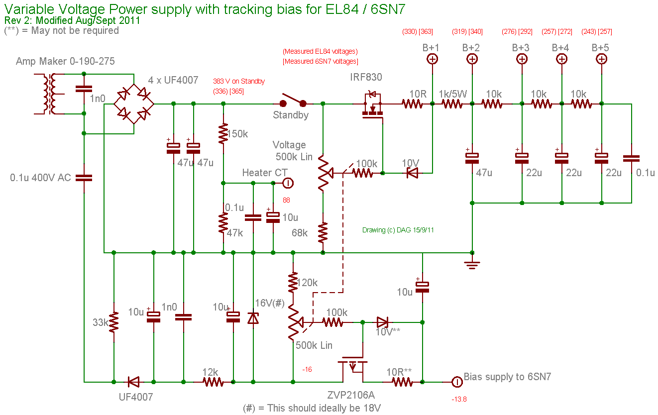
I've had good results using the uppermost circuit in the attached diagram to implement variable B+ in a cathode biased tube guitar amp output stage. I'm now looking to implement a similar control in a fixed bias amp, and will therefore need a means of adjusting the grid bias voltage in tandem with B+.

The second circuit in the attachment claims to do just that, but I'm a little confused over the implementation. Why has the designer chosen to take a fixed voltage output form the MOSFET followed by a resistive divider, rather than applying a variable reference to the gate, as per the first circuit? Furthermore, what is the purpose of the MOSFET here? If the bias supply were strong enough, surely a simple resistive divider would be all that's required?

Any pointers would be very much appreciated!
 

Attachments

  • VVR_schematic.jpg
    VVR_schematic.jpg
    55 KB · Views: 147
Thinking aloud, is this basically a voltage follower to prevent interaction between the traditional bias adjust pot and the new bias tracking pot?
 
MatthewF said:
Thinking aloud, is this basically a voltage follower to prevent interaction between the traditional bias adjust pot and the new bias tracking pot?
No, it's not a proper source follower since the drain supply is not independant. I don't really understand this circuit. As much as I understand the need for a bufer after the B+ pot, I don't see it for bias.
Just guessing, taking bias from a 1Meg pot is a bit risky, because of grid leak, so this was a half-ased attempt to reduce the output resistance, but I don't see it working as expected.
It seems this scheme is based on the assumption that the bias voltage must be linearly dependant on B+, which is far from proved. I would keep the two pots separate. then you could use a much lower value pot for bias (50-100k).
 
Looks like they were trying to do something like this, but goofed the drawing.
VVR-updated.gif

A PNP transistor could be used instead of a P-MOSFET, of course.
 
Thanks for the input! The scheme in Merlin's post does indeed look a lot more sensible!

abbey road d enfer said:
It seems this scheme is based on the assumption that the bias voltage must be linearly dependant on B+, which is far from proved. I would keep the two pots separate. then you could use a much lower value pot for bias (50-100k).

I agree, it's a big leap to assume that the relationship between B+ and bias is linear. I would, however, like to stick with a one-knob solution as the intention is to provide the player with a "headroom" control, such that a degree of natural compression can be dialled in without running at full tilt. To this end, perhaps a pair of stepped attenuators on a 2-deck rotary switch would work better; one deck for B+ and one for bias. The values could be inferred from tube curves or established empirically. One could even add a third deck to control input drive.
 
MatthewF said:
Thanks for the input! The scheme in Merlin's post does indeed look a lot more sensible!

abbey road d enfer said:
It seems this scheme is based on the assumption that the bias voltage must be linearly dependant on B+, which is far from proved. I would keep the two pots separate. then you could use a much lower value pot for bias (50-100k).

I agree, it's a big leap to assume that the relationship between B+ and bias is linear. I would, however, like to stick with a one-knob solution as the intention is to provide the player with a "headroom" control, such that a degree of natural compression can be dialled in without running at full tilt. To this end, perhaps a pair of stepped attenuators on a 2-deck rotary switch would work better; one deck for B+ and one for bias. The values could be inferred from tube curves or established empirically. One could even add a third deck to control input drive.
Indeed, it's certainly feasible; just be ready for some tweaking...
Fortunately, it is not so difficult to twist the law of porentiometers with resistors connected between wiper and one end.
 
Reading a bit further on this topic, it would appear that some people recommend implementing an entirely separate bias supply (instead of the ubiquitous "back biasing" diode on the HT winding) when adding a MOSFET voltage scaling circuit.

Literature relating to one commercial design implies that the resistive divider commonly used to set bias voltage in traditional designs renders the circuit incapable of supplying enough current to the MOSFET regulator. At this stage I'll need to revise my MOSFET theory before I can form an opinion on that matter! Either way, there are plenty people who say everything runs just fine with a MOSFET following the old school bias supply scheme...

Matthew
 
MatthewF said:
Reading a bit further on this topic, it would appear that some people recommend implementing an entirely separate bias supply (instead of the ubiquitous "back biasing" diode on the HT winding) when adding a MOSFET voltage scaling circuit.

Literature relating to one commercial design implies that the resistive divider commonly used to set bias voltage in traditional designs renders the circuit incapable of supplying enough current to the MOSFET regulator. At this stage I'll need to revise my MOSFET theory before I can form an opinion on that matter! Either way, there are plenty people who say everything runs just fine with a MOSFET following the old school bias supply scheme...

Matthew
It all depends on the branch current in the final voltage divider. Deriving the bias voltage from the HV windings means a lot of energy wasted in resistors.
Typically, the bias voltage divider should operate with a few mA; this will appear in the first ballast resistor, with a corresponding dissipation.
In the previous schemo, the first voltage drop is created by a capacitor; as a consequence there is no energy dissipated.
 
I guess that's why we often see a tap on the HT winding at lower potential - so that we don't have to generate excessive heat in the ballast resistor? The Fender AB763 schematic (attached) uses such a tap, and appears to keep dissipation in the 470R series resistor below 1W.

What I'm trying to get my head around is how the introduction of a MOSFET circuit as above, inbetween the AB763's 10k pot and 220k bias resistors, could make the situation worse, to the extent that an entirely separate bias winding and rectifier is required. The extra voltage divider which provides the reference to the gate will naturally draw a little extra current, but using a 1M pot should ensure that's negligible. Perhaps there's an issue with the MOSFET dropping too much voltage to supply sufficient -ve grid bias voltage to the tubes when it's inserted into a pre-existing circuit such as the AB763. Time to look at some datasheets!
 

Attachments

  • Deluxe-AB763-schematic.pdf
    485.1 KB · Views: 10
> I don't really understand this circuit.

Me neither, except doesn't it say "no powersliding enabled"? So you can't trim the B+ because the Bias won't follow and the tubes will shut-off cold when you turn B+ from 10 to 8?

> trying to do something like this, but goofed

That "like this" one makes sense (of course).

But the dual-pot should not be necessary, and I'd be concerned about the 400VAC--50VDC converter shifting with variable loading.

A more clever approach is an inverting amplifier. Say the "full power" condition is 400V and -45V. Get the bias from an amplifier with gain of -0.1125. When you turn-down to 200V B+, the bias will shift to -22.5V. This is not quite right, but over a fair range will be close-enough.

I'm sure I've seen that somewhere.

A little fixed bleed to make the bias change less than the B+ change will avoid going cold as you turn down. A slightly hot bias is fine when B+ is low.
 
this Eggbeater Tourmaster has B+/Bias trickery going on,

http://groupdiy.com/index.php?topic=57720.msg735408#msg735408

too much circuitry, eh?

a regulated pwr supply might not be the best sounding thing on earth for a guitar amp, you are modulating the pwr supply with the guitar, so you are actually playing the power supply and all it's idosynchronocities, can i say that?  :D

mixing high voltage and mosfets is scary, would rather build a bullet proof Fairchild 670 tube regulator with a dual pot with a Fender style bias scheme on the second section of the pot, you can get dual pots with different resistances in each section, like 100K for B+ control and 25K for bias control,

other possible solutions-

run a 6.3 VAC xfmr for heaters, use a mini variac to control the B+ voltage/bias tap on the step up xfmr , this would be simple and very  reliable,


CJ said:
a regulated pwr supply might not be the best sounding thing on earth for a guitar amp, you are modulating the pwr supply with the guitar, so you are actually playing the power supply and all it's idosynchronocities, can i say that?  :D

I can't say that out loud, but I know what you mean! I was hoping that any 'feel' associated with the power supply would be preserved, at least to some degree, due to the fact that the MOSFET's gate is referenced to a fraction of the voltage on the first filter cap. So, if the rectifier sags, so does the reference at the gate, and so does the scaled down B+.

Of course, when running at lower power the rectifier won't be sweating much, so we can't expect this effect to scale down to low output levels, but hopefully things will still feel nice when running at or near near full power?
 
CJ said:
mixing high voltage and mosfets is scary, would rather build a bullet proof Fairchild 670 tube regulator with a dual pot with a Fender style bias scheme on the second section of the pot, you can get dual pots with different resistances in each section, like 100K for B+ control and 25K for bias control,

other possible solutions-

run a 6.3 VAC xfmr for heaters, use a mini variac to control the B+ voltage/bias tap on the step up xfmr , this would be simple and very  reliable,

I like both of those ideas, especially the variac. Sadly I'm not in a position to try those out on the bench right now as I've already sourced transformers, chassis etc. for an AB763 build, which is the amp I'd like to add the power adjust circuit to.

That Fairchild PSU is interesting. If that EL34 (V302 on the schem) has to dissipate what I think it does, then 100mA B+ dropped from 400v to 100v would generate 30W in that valve, so we'd need something bigger than an EL34 for a 2x6V6 guitar amp? That might be a hard sell to the musician who's deliberately choosing a smallish amp...

 
PRR said:
A more clever approach is an inverting amplifier. Say the "full power" condition is 400V and -45V. Get the bias from an amplifier with gain of -0.1125. When you turn-down to 200V B+, the bias will shift to -22.5V. This is not quite right, but over a fair range will be close-enough.

This sounds like a rather good idea (for so long as one is happy mixing transistors with high voltages). I've been trying to imagine an elegant implementation of such an amplifier. I guess we'd need bi-polar supply rails - hopefully the-existing B+ and bias supplies would suffice. I'm thinking of another MOSFET configured as an inverting amplifier, with the variable B+ from the first MOSFET serving as the input. I'll try to catch up on my theory and sketch something.
 
PRR said:
I'd be concerned about the 400VAC--50VDC converter shifting with variable loading.
That's why the bias supply in that particular example is regulated with a 16 Zener.
 
If zener regulators could be used to create stable supply rails from the standard B+ and bias supplies, then perhaps a suitable op-amp could be used as the amplifier in the scheme that PRR described. A quick google threw up the OPA445 as a starting point -  http://www.ti.com/lit/ds/symlink/opa445.pdf

I'd imagine that could work in theory, but the potential failure modes would have to be understood well!
 
Question for MatthewF:  Is the overall goal here to be able to adjust your B+  over a wide range? 

And, how far do you plan on dropping the B+?  What I'm getting at is that if you will be dropping it very low (100-250VDC)  - is there really a need to be using fixed bias?    Versatility?  I can see wanting to go low then have it be fixed bias for the highest output settings.  Is cathode bias design not cutting it for your purposes?

 
Good question! The goal is indeed to be able to alter B+ over a wide range - perhaps down to 100v as you said.  (I have a 5W single-ended cathode-biased amp here with variable B+ down to 30v - it still makes healthy sound even at that level!)

I'm pursuing the fixed bias approach for sonic reasons - I'm particularly fond of the way the Fender Deluxe Reverb distorts when pushed, and am trying to get some of this tone at less deafening volume levels. (Not bedroom quiet, but more sound engineer friendly!)

I realise that using cathode bias would be the most elegant way to solve my problem, and to that end I plan to compare cathode bias vs fixed bias (at full B+) once I've finished assembling the amp. If the amp sounds good to me with cathode bias then I'll happily go with that scheme. I am, however, aware that all my favourite guitar amps to date have been based on fixed-bias, push-pull pentode output stages, all of which are bloody loud!
 
I plan to compare cathode bias vs fixed bias (at full B+) once I've finished assembling the amp.

That seems to be critical spot where people that like fixed bias say they don't care for cathode bias.  Interesting though that Deluxe uses tube rectifier which already works against the super fast edgy sound of SS diode and fixed bias (High plate voltage) sound.  In the Deluxe (BF) it seems to be just the right combination to keep it smooth (tube rectifier) but clean, fast and cutting (high plate voltage and fixed bias).  SRV heaven.  Hopefully cathode bias won't lose too much of that.

If I had the PT nobody makes - Plate ONLY - LOW (meaning guitar amp voltages and not the traditional 1500V or so HV)  And make it an autoformer - ie a variac I'd be set!    Some industrial supplies make compact variacs you could mount without too much space but they are crazy $$.    Wish somebody would make one instead of all those fancy Power Soak things.  I think having to mention using a separate filament transformer just kills it for everybody.  Filament iron is cheaper than Power Soak though.
 

Latest posts

Back
Top