? about generic tube mic PSU and M49 build (updated).

GroupDIY Audio Forum

Help Support GroupDIY Audio Forum:

This site may earn a commission from merchant affiliate links, including eBay, Amazon, and others.

Bowie

Well-known member
Joined
Jun 22, 2012
Messages
368
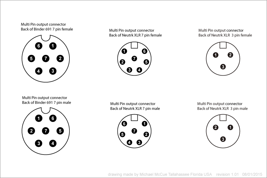
  I bought one of Oliver's kits a while ago and I've finally got most of it built.  However, I'm trying to re-wire the cable to go from a 7-pin XLR to a Binder and I'm lost.  The PSU is a generic tube mic PSU http://tab-funkenwerk.com/id203.html and I have no idea how to wire it.  Through testing I found that the heater is pin 2 from the PSU and the mic is supposed to receive the heater on pin 4.  I don't know about the rest though.  Any help in the right direction would be great as this has been the most frustrating build I've undertaken.  Because there's no support I've had to PM GDIY members who built these just so I could get this far, but haven't found anyone who has used this PSU that Oliver sent with my mic.
Thanks!
 
It will probably be easier if you open up the PSU to see where the connections come from.

The you can use a VOM to confirm where the ground pin is and where the various voltage pin outs are.

If it were me, I would draw up a diagram that detailed the pin numbers on the backs of both pairs of connectors because I always get myself confused if I do not.

This way you can slowly and carefully map out which XLR pin relates to which Binder pin... and of course this has to comply with the layout in the mic itself.

IIRC most XLRs have pin numbers sequenced in the opposite direction (clockwise or counter clockwise) of Binder connectors so that adds a layer of potential confusion.

Make a diagram with the connector in the PSU and the connector in the mic and identify their pinouts and then work your way through the cable connections making sure to keep track of the way the numbers are sequenced at the solder tabs.

 
Bowie,

The pin-out for your PSU is:

1 – B+ (120V)
2 – Heater (6.3V)
3 – Polarity (0-120V)
4 – GND
5 – Audio -
6 – Audio +
7 – GND

Personally, I wouldn't build a weird cable to match up a different pin-out on the PSU. I'd go for the most straightforward solution:

Remove the top case of the PSU to expose the wiring from PCB to connectors. Mark the wires if you need to, but you should be able to remember all of them from their colours after you've identified them (B+ is RED, Heater is YELLOW, GND is WHITE etc...). Then desolder all the wires from the female 7-pin connector, and rewire them one by one to match the pin-out of your microphone. If PIN4 is the heater on your microphone, rewire the yellow wire to PIN4 inside the PSU etc.

This should only take you around 30mins, and there's zero danger since you're working on an unplugged/unpowered PSU.

Then build a straight wire cable using a Neutrik 7-pin MALE and Binder 691 7-pin FEMALE, connecting each pin to its corresponding number (1 to 1, 2 to 2, 3 to 3, 4 to 4 etc.), and tie the shield of the cable to the GND pin and connector casings on both sides of the cable.

I'd also recommend swapping out the 7-pin FEMALE connector on the PSU. Neutrik cable connectors and the Chinese PSU connectors don't match well. The slightest movement of the connector casings can cause voltage spikes, or give you a mic who's signal cuts out easily. Neither is good for your tube. Go for a real Neutrik or Switchcraft.

Lastly, make sure your polarity is wired correctly. You want Audio+ on PIN2, and Audio- on PIN3 of the 3-pin XLR.

If you have any more questions, feel free to ask. If ever you're not comfortable with this re-wiring, post a pic of your PSU from the top (case open), and I'll mark the wires for you. Also provide the full pin-out of your microphone, and we can label everything to give you an easy guide to follow.
 
trans4funks1 said:
Make a diagram with the connector in the PSU and the connector in the mic and identify their pinouts and then work your way through the cable connections making sure to keep track of the way the numbers are sequenced at the solder tabs.
Thank you for the advice!

Banzai said:
Bowie,

The pin-out for your PSU is:

1 – B+ (120V)
2 – Heater (6.3V)
3 – Polarity (0-120V)
4 – GND
5 – Audio -
6 – Audio +
7 – GND

Personally, I wouldn't build a weird cable to match up a different pin-out on the PSU. I'd go for the most straightforward solution:

Remove the top case of the PSU to expose the wiring from PCB to connectors. Mark the wires if you need to, but you should be able to remember all of them from their colours after you've identified them (B+ is RED, Heater is YELLOW, GND is WHITE etc...). Then desolder all the wires from the female 7-pin connector, and rewire them one by one to match the pin-out of your microphone. If PIN4 is the heater on your microphone, rewire the yellow wire to PIN4 inside the PSU etc.

This should only take you around 30mins, and there's zero danger since you're working on an unplugged/unpowered PSU.

Then build a straight wire cable using a Neutrik 7-pin MALE and Binder 691 7-pin FEMALE, connecting each pin to its corresponding number (1 to 1, 2 to 2, 3 to 3, 4 to 4 etc.), and tie the shield of the cable to the GND pin and connector casings on both sides of the cable.

I'd also recommend swapping out the 7-pin FEMALE connector on the PSU. Neutrik cable connectors and the Chinese PSU connectors don't match well. The slightest movement of the connector casings can cause voltage spikes, or give you a mic who's signal cuts out easily. Neither is good for your tube. Go for a real Neutrik or Switchcraft.

Lastly, make sure your polarity is wired correctly. You want Audio+ on PIN2, and Audio- on PIN3 of the 3-pin XLR.

If you have any more questions, feel free to ask. If ever you're not comfortable with this re-wiring, post a pic of your PSU from the top (case open), and I'll mark the wires for you. Also provide the full pin-out of your microphone, and we can label everything to give you an easy guide to follow.
Banzai, I can't thank you enough for taking the time!  Invaluable info and having it brings a huge relief as I finally feel like I can see the light at the end of the tunnel on this project.  I'll dig into this over the next few days.
 
No problem; what you have left to do is the easy part (much easier than building the microphone!).

If ever you do decide to swap the 7-pin connector on the PSU, the part you want is: http://www.mouser.ch/Search/Refine.aspx?Keyword=nc7fp-1

Not all of the Neutrik's use the same footprint, so with some models the mounting holes don't line up with the PSU casing. The NC7FP-1 will mount and line up perfectly straight.
 
Here is an assembly of the clip art elements I use in the diagrams I make for myself. They may be helpful as you map out your circuit:

Multi-Pin-Connector-Symbols.jpg


These views all show the back side of the connectors where you actually solder the wires.

If it were me, I would feel compelled to confirm that any suggested pin out is indeed the pin out in the appliance being worked on. In other words, I would use Banzai's list as a start and then confirm that by first hand investigation.

It occurs to me that you may have already assembled your mic completely. If this is the case it will be even more important that you trace out and map everything correctly.

Oliver's schematics usually followed Binder's convention of illustrating the pin out from the pin, or front side, rather than the back side where the solder tabs are, so it can get really confusing if you are not fastidious about keeping track of the actual pin numbers on the actual connector.

As Banzai has suggested, it is is nice if you use the same pin numbers throughout the circuit. If you have already wired up the mic body, and the PSU is already wired up, you may wish to move some of the wires, on one or the other, around to correspond with a cable where, for example, pin 1 on the male end goes to pin 1 on the female end. In any event, if you map out the circuit you will see what choices you have.


Banzai said:
No problem; what you have left to do is the easy part (much easier than building the microphone!).

If ever you do decide to swap the 7-pin connector on the PSU, the part you want is: http://www.mouser.ch/Search/Refine.aspx?Keyword=nc7fp-1

Not all of the Neutrik's use the same footprint, so with some models the mounting holes don't line up with the PSU casing. The NC7FP-1 will mount and line up perfectly straight.
Thanks again!  Yea, the first thing I noticed was the poor quality of the 7-pin XLRM  and though I tend to be very gentle with my gear, I could easily see it becoming damaged at some point so I'll likely just build an entirely new cable and change the connector at the PSU.  I know what you mean about Neutriks sometimes not playing well with others.

trans4funks1 said:
Here is an assembly of the clip art elements I use in the diagrams I make for myself. They may be helpful as you map out your circuit:

Multi-Pin-Connector-Symbols.jpg


These views all show the back side of the connectors where you actually solder the wires.

If it were me, I would feel compelled to confirm that any suggested pin out is indeed the pin out in the appliance being worked on. In other words, I would use Banzai's list as a start and then confirm that by first hand investigation.

It occurs to me that you may have already assembled your mic completely. If this is the case it will be even more important that you trace out and map everything correctly.

Oliver's schematics usually followed Binder's convention of illustrating the pin out from the pin, or front side, rather than the back side where the solder tabs are, so it can get really confusing if you are not fastidious about keeping track of the actual pin numbers on the actual connector.

As Banzai has suggested, it is is nice if you use the same pin numbers throughout the circuit. If you have already wired up the mic body, and the PSU is already wired up, you may wish to move some of the wires, on one or the other, around to correspond with a cable where, for example, pin 1 on the male end goes to pin 1 on the female end. In any event, if you map out the circuit you will see what choices you have.
Thanks! I agree and will follow your and Banzai's recommendation on making the pin-out uniform between mic and  PSU.  I have  soldered all of the components (save for tube and capsule) and followed the original physical wiring layout and braid as Oliver recommended.  I've not soldered the Binder at the mic yet but I like Banzai's idea of making the PSU match the mic so I think I'll order some Neutriks and resume this in a week when they arrive.

I'll report back.  :)


Update;  it went perfectly!  Well, as perfect as it can get when you're working on it from 1am to 3am each night (I had to correct the wiring twice).  Mic sounds gorgeous and is extremely quiet.  Thanks for the help!!
 
So, this went extremely well and the mic runs quiet.  Thanks!  However, I'm wondering is there any benefit from upgrading any of the components in this power supply?  The caps are cheapie Xia-Hui caps and I had to fix some of the soldering, which was sloppy.  The cool thing was that the polarity PCB has Oliver's name on it so I see he had a hand in the design of this PSU, though it is his standard-quality offshore offering.
I upgraded the capsule and some of the caps in the mic itself, so is it worth upgrading anything in the PSU?
 
Back
Top