timkroeger
Member
Hey everyone,
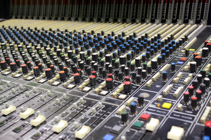
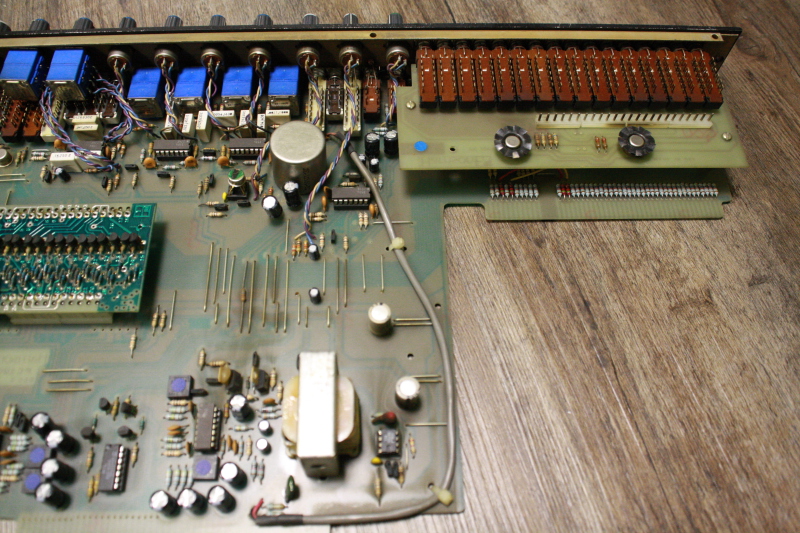
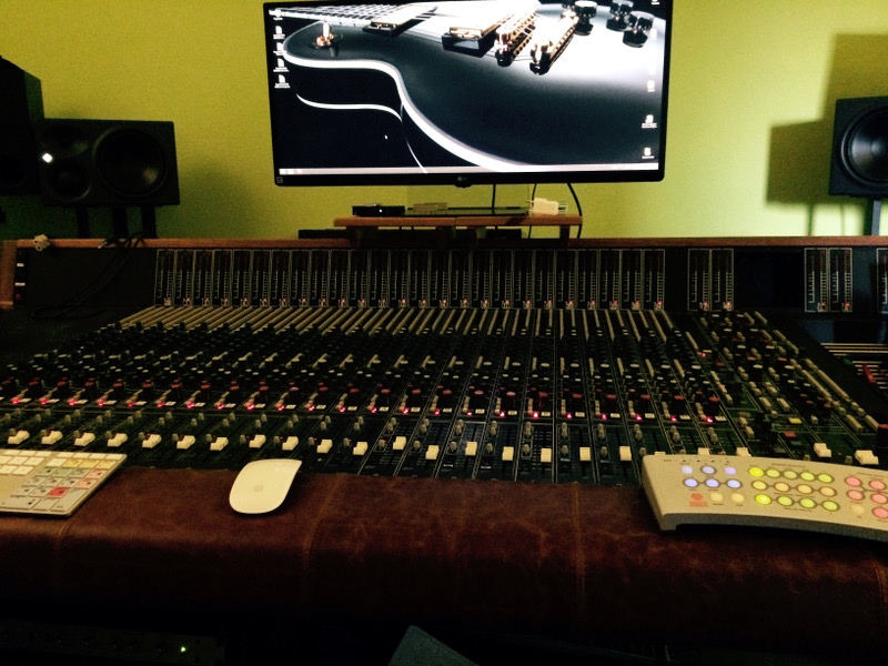
I'm currently restoring a Harrison 3232 that I bought from a nice guy in Hamburg for my control room. It's currently loaded with 25 channels and seems to be in pretty good shape. Recapped some time ago and only a small burnt area in the vicinity of the phantom power switch. Someone modded that section and upon removal seems to have connected the wrong leads...
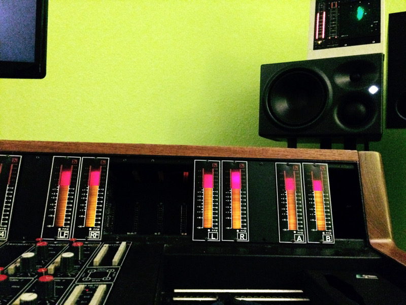
Anyway all channels except channel #6 pass audio coming from multitrack A return and feed the 36 segment") meters in Return Mon and Return Mix mode. A quick FET card and channel strip swap with #6 confirmed that the issue lies with the I/O board and FET and edge connectors are fine. We'll see. I thought I'll post some pictures and document what I'm doing and have already done; and maybe if I get stuck somewhere, someone here can hopefully help me out. I've learned a lot from previous Harrison posts already (Frank!!!) and studied the manual/schematics three times by now - I think. It's still a little alien to me though
meters in Return Mon and Return Mix mode. A quick FET card and channel strip swap with #6 confirmed that the issue lies with the I/O board and FET and edge connectors are fine. We'll see. I thought I'll post some pictures and document what I'm doing and have already done; and maybe if I get stuck somewhere, someone here can hopefully help me out. I've learned a lot from previous Harrison posts already (Frank!!!) and studied the manual/schematics three times by now - I think. It's still a little alien to me though
Since I'm missing a few channels I was searching around and found someone who offers channels from an early 4032 but he claims that they are running on +/-24V for increased headroom. No mod, just very early 4032. I've seen PSUs with warning lights for only +/-15V and +/-24V but my PSU features +/-15V, +/-18V and -24V. From the docementation I learned that a lot of the logic seems to rely on the -18V / -24V difference so I'm curious: do you know of these earlier models or is this a misunderstanding?
It would be awesome to increase the number of channels since I have a lot of outboard and want to hook up an Orion 32 for the digital stuff and my Studer A80 for analog.
So what did I do already:
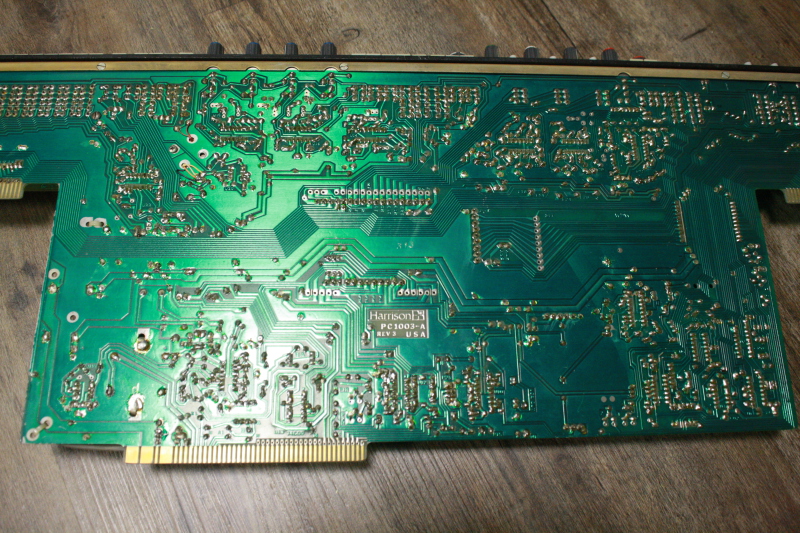
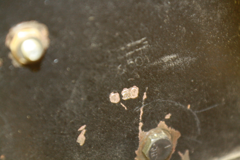
I found a number stenciled into the inside of the right flange which reads 050; is that the serial number or is it to be found elsewhere? It has the black dbx 202 cans so A model it is?
I'll post some more pictures and probably some closeups of the strips later!
Cheers
Tim
I'm currently restoring a Harrison 3232 that I bought from a nice guy in Hamburg for my control room. It's currently loaded with 25 channels and seems to be in pretty good shape. Recapped some time ago and only a small burnt area in the vicinity of the phantom power switch. Someone modded that section and upon removal seems to have connected the wrong leads...
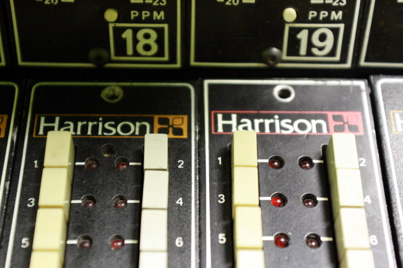
Anyway all channels except channel #6 pass audio coming from multitrack A return and feed the 36 segment
meters in Return Mon and Return Mix mode. A quick FET card and channel strip swap with #6 confirmed that the issue lies with the I/O board and FET and edge connectors are fine. We'll see. I thought I'll post some pictures and document what I'm doing and have already done; and maybe if I get stuck somewhere, someone here can hopefully help me out. I've learned a lot from previous Harrison posts already (Frank!!!) and studied the manual/schematics three times by now - I think. It's still a little alien to me though
Since I'm missing a few channels I was searching around and found someone who offers channels from an early 4032 but he claims that they are running on +/-24V for increased headroom. No mod, just very early 4032. I've seen PSUs with warning lights for only +/-15V and +/-24V but my PSU features +/-15V, +/-18V and -24V. From the docementation I learned that a lot of the logic seems to rely on the -18V / -24V difference so I'm curious: do you know of these earlier models or is this a misunderstanding?
It would be awesome to increase the number of channels since I have a lot of outboard and want to hook up an Orion 32 for the digital stuff and my Studer A80 for analog.
So what did I do already:
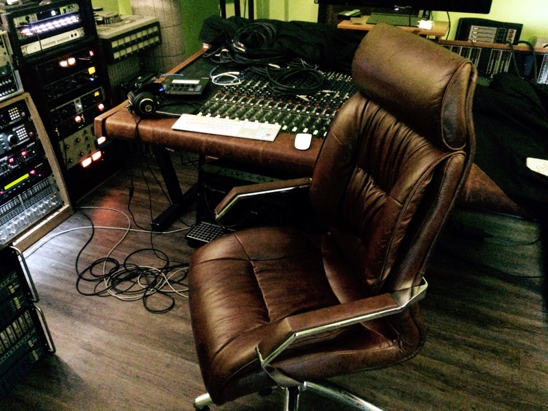
- Had the right stand patched up - new bolt replacing a broken nut
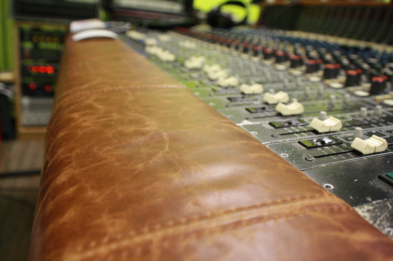
- New leather for the armrest
- Sanded and repainted the wooden sides
- Fixed PSU hookup which got damaged during transport
- Fixed some meter cabling
- Measured PSU, slowly brought up the console channel by channel
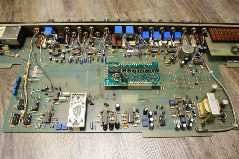
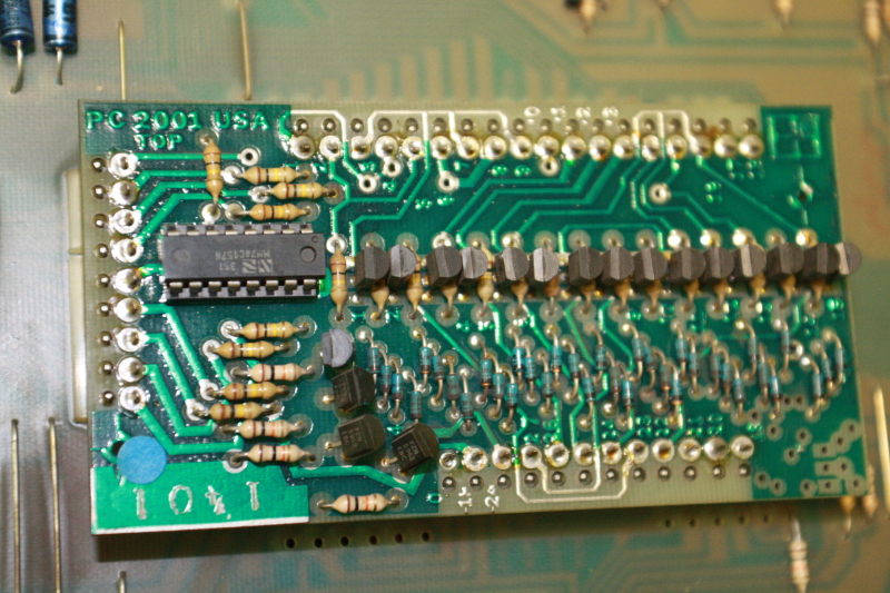
- Replaced a few 74C157 with CD40257BE as suggested here by Martin B. Kantola in 2009 to rule out some strange behaviour
I found a number stenciled into the inside of the right flange which reads 050; is that the serial number or is it to be found elsewhere? It has the black dbx 202 cans so A model it is?
I'll post some more pictures and probably some closeups of the strips later!
Cheers
Tim