


I've been toying with this idea for a bit, as I'm currently sitting on a few stuffed Harrison Ford Filter pcb's and wanted a way to use them in my 500 series rack without making them an entire module. I also have a few 10k linear center detent pots sitting around, a couple of 2503's, and recently have started winding some inductors on rm8 cores. So, next logical step is to try and pair the Harrison Ford Filter board with the API 553 eq circuit (plenty of schems out there, one on Classic API or PeteC's 5003 schem floats about) in a 500 series chassis.
Here's a block diagram of what I've come up with (mocked up in the always useful Microsoft Paint), details below.
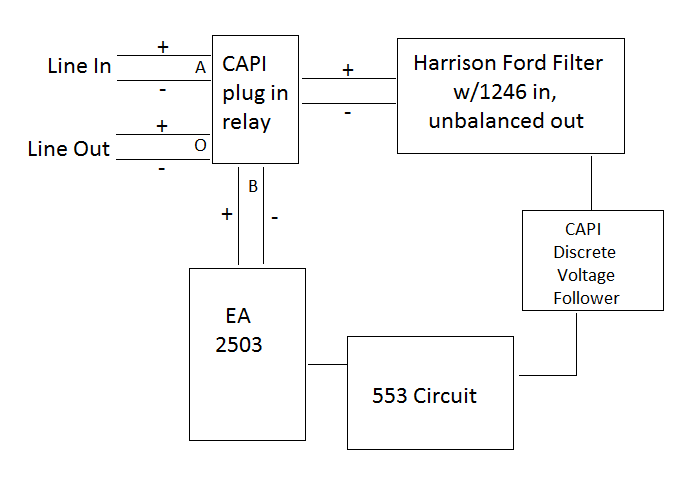
I decided to use "building block" circuits that others much more knowledgeable have made available. I wanted the option to have a full bypass, so line in first hits the CAPI plug-in relay (http://classicapi.com/catalog/product_info.php?cPath=102&products_id=195). This switches the output between the line in and EA2503 out.
Line in then goes to the Harrison Ford Filter PCB. This PCB offers provisions for balanced line in and out, but I'm only going to use the balanced line in to a THAT 1246, taking an unbalanced feed after the filters. These two filters can be switched in and out with a pushbutton switch.
Unbalanced out from Harrison Ford Filter PCB goes to a CAPI discrete voltage follower (http://classicapi.com/catalog/product_info.php?cPath=71_72&products_id=221) to act as a buffer between the two circuits. The unbalanced out from the discrete voltage follower feeds the 553 circuit, which is currently a direct copy of the schematics. Out to a 2503 wired 1:3, whose output feeds the other side off the CAPI plug in relay.
I threw together a quick schematic in KiCad. This would house the 553 circuit and the rest of the inner workings/connections, wired up to a 500 series edge connector PCB (http://classicapi.com/catalog/product_info.php?cPath=87_88&products_id=402). Please note, most components are unlabeled, and I really have not double checked it at all.
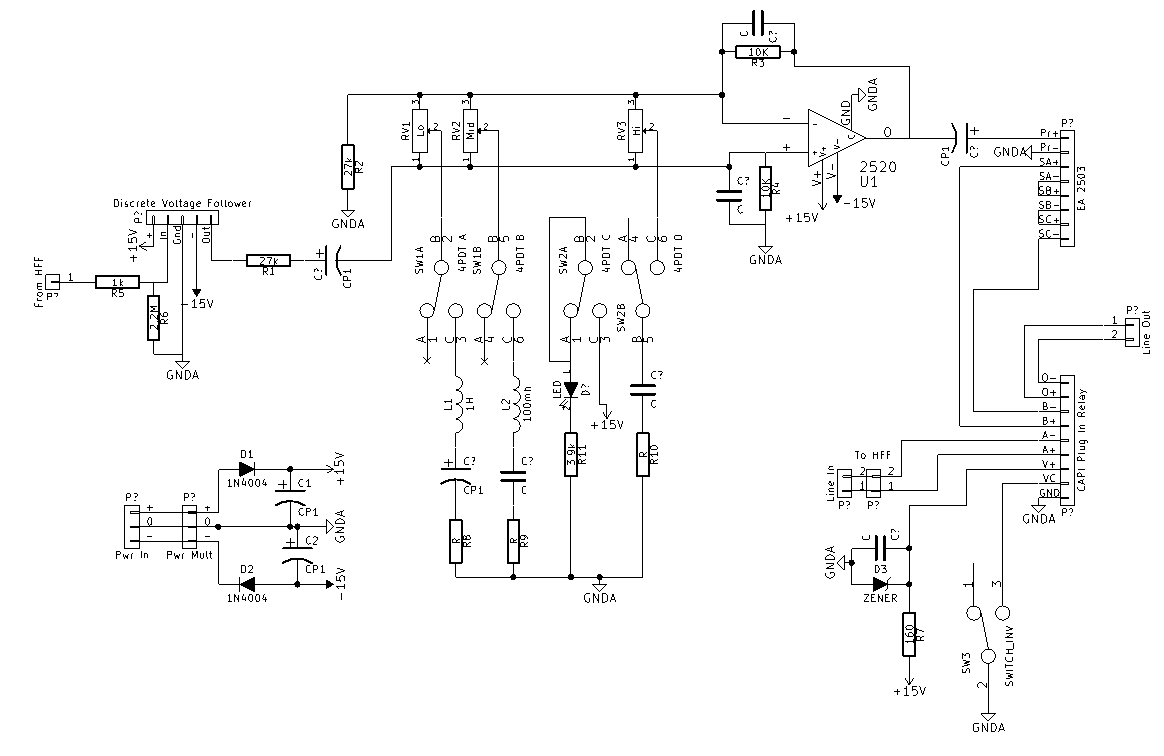
Basically, this is a direct copy of the 553 schematic, with provisions for the "building blocks" added in. For the relay power, I copied that little bit from the vp312 DI schematic publicly available on the CAPI site. It seems to make sense.
My idea for general faceplate layout:
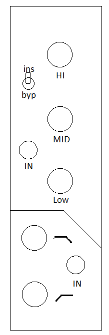
I'll post some more tomorrow on the module layout, but wanted to start getting some feedback on the general idea and how best to implement it.
Another note: I have no idea what I'm doing, but I've gathered enough knowledge to conceptually piece things together. The more input that people provide, the more I learn.
Much appreciated,
Keith
Edited: added a bunch of links
")


