Implementing diodes to drop heater voltage.

GroupDIY Audio Forum

Help Support GroupDIY Audio Forum:

This site may earn a commission from merchant affiliate links, including eBay, Amazon, and others.

Bowie

Well-known member
Joined
Jun 22, 2012
Messages
368
Backstory; just finished another LA2A and everything seems kosher, except the heaters are just north of 7v (instead of 6.3).  I've read that one of the best ways to adjust this is to run 3amp silicon diodes in series to get a .7v drop but everything I've read is a passing mention and I'd really like to get a better understanding before going forward.  Would it look like this on each of the heater wires:
PT-----Diode->|--------parallel tubes

Feels like something is missing but I don't know, hence my asking.
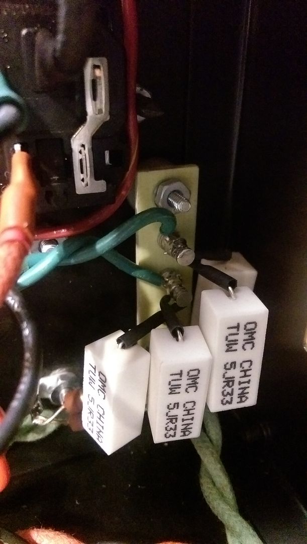
I also have an artificial CT using resistors, would the diodes go before or after that.  And, can you recommend a specific diode for this application?
Thanks in advance!
 
Diode drop of ca. 0.6V per SI-diode is usable only for DC heaters.

For AC heating, you can either just ignore the over voltage (it's still within 10% of recommended, and tubes aren't fussy) - or you can use a resistor to drop voltage a bit. Use ohm's law - this is a good opportunity to understand what that one is about...

Jakob E.
 
moamps said:
gyraf said:
Diode drop of ca. 0.6V per SI-diode is usable only for DC heaters.

The anti-parallel diode pair will do the job for AC heater voltage drop.
Could you explain that one to me?  How I would wire that up?  Thanks.
 
resistor is better,  more dependable,

remember that when those tubes start up they are like a dead short,

many amps will flow, diodes will not like this very much over time,

plus, heat is heat, power is power, unless you use reactance

so if you drop a 4 amp heater circuit by .6, you still have 2.4 watts,

when semiconductors get hot, they let more current through,

use a 10 watt .15 ohms resistor, which they don't make often,

so parallel two .33  five watters

hi tek solution-use a .1/377=265 micro Henry choke made out of #21

some crazy freak around here even took a few turns off the 6.3 winding,  :D

here is the heater circuit thread, yes they use diodes sometimes,

http://groupdiy.com/index.php?topic=57166.msg728663#msg728663


Replacing my previous post as I realized that paralleling the 5watters was to replace the 10w.  However, just to confirm, these are in placed in series with the heater wires, and can be placed after my false center tap resistor legs?
 
> I've read that one of the best ways to adjust this is to run ... silicon diodes

Where do silly ideas like this get started??

Diode drop adds BUZZZ to your hummm.

Listen to CJ. (Resistors, not chokes or de-winding {unless that's your thing}).
 
PRR said:
> I've read that one of the best ways to adjust this is to run ... silicon diodes

Where do silly ideas like this get started??

Diode drop adds BUZZZ to your hummm.

Listen to CJ. (Resistors, not chokes or de-winding {unless that's your thing}).
Guitar amp forums of course, where misinformation goes to breed.  That's why I came here before trying it.

Now, these are going in-series on the heater wires, right after the PT, correct?
 
PRR said:
> I've read that one of the best ways to adjust this is to run ... silicon diodes
Where do silly ideas like this get started??
Diode drop adds BUZZZ to your hummm.
Listen to CJ. (Resistors, not chokes or de-winding {unless that's your thing}).

I have used anti-parallel diodes (high power schottky diodes from old PC UPS) for AC heater drop several times without any  problem with buzz. 
 
CJ said:
resistor is better,  more dependable,

remember that when those tubes start up they are like a dead short,

many amps will flow, diodes will not like this very much over time,

plus, heat is heat, power is power, unless you use reactance

so if you drop a 4 amp heater circuit by .6, you still have 2.4 watts,

when semiconductors get hot, they let more current through,

use a 10 watt .15 ohms resistor, which they don't make often,

so parallel two .33  five watters

hi tek solution-use a .1/377=265 micro Henry choke made out of #21

some crazy freak around here even took a few turns off the 6.3 winding,  :D

here is the heater circuit thread, yes they use diodes sometimes,

http://groupdiy.com/index.php?topic=57166.msg728663#msg728663

Just saying a quick "Thanks!" to CJ for the specifics.  The paralleled .33ohm resistors brought me down to 6.2v, so I'm golden on this one.  Took a bit of making room for these hot little buggers but it was a pretty simple solution, didn't add any noise, and cost a couple bucks.
Also, thx to everyone for the replies.
 
thanks for all this information! i'm going to try this as well.

CJ, who was that crazy freak? i won't lie about how excited that idea is to me….. ;D ;D ;D ;D ;D
 
Warning!  groupDIY  consensus was that this was a foolhardy endeavor and not a viable option compared to the price of purchasing the correct transformer>  ;D

http://groupdiy.com/index.php?topic=58643.msg745580#msg745580
 
soundsactive said:
thanks for all this information! i'm going to try this as well.

CJ, who was that crazy freak? i won't lie about how excited that idea is to me….. ;D ;D ;D ;D ;D
As I promised you in PM, here's the pic of the resistor set up.  Xfo heaters into the top posts w/ parallel .33ohm resistors in series with the heater wire which splits in two directions (tubes and meter lamp) at the bottom junction.  False center tap (100ohm resistors to ground) seen poking out in the lower left.  This turret board is normally used for IEC hookup in the LA-2A but I didn't need it for that so I arranged things to be a little cleaner here.

They get hot so let them sit in a spot that heat can dissipate upward and where nothing is going to rub against them.  They are Ohmite 5w, 5% wirewound.  You can get the Vishay Mills which are much smaller, but you're looking at over $3 or $4ea vs 80 cents.

IMAG2933_zpszflkkmzz.jpg
 

Latest posts

Back
Top