Gates Sta Level - ptp

GroupDIY Audio Forum

Help Support GroupDIY Audio Forum:

This site may earn a commission from merchant affiliate links, including eBay, Amazon, and others.

Biasrocks

Well-known member
Joined
Jun 19, 2004
Messages
1,827
Location
Windsor, On, Canada
I'm going to attempt a PTP build of the Gates Sta-Level, the 1960's schematic version.

http://www225.pair.com/audio/waltzingbear/Schematics/Gates/Sta_Level.htm

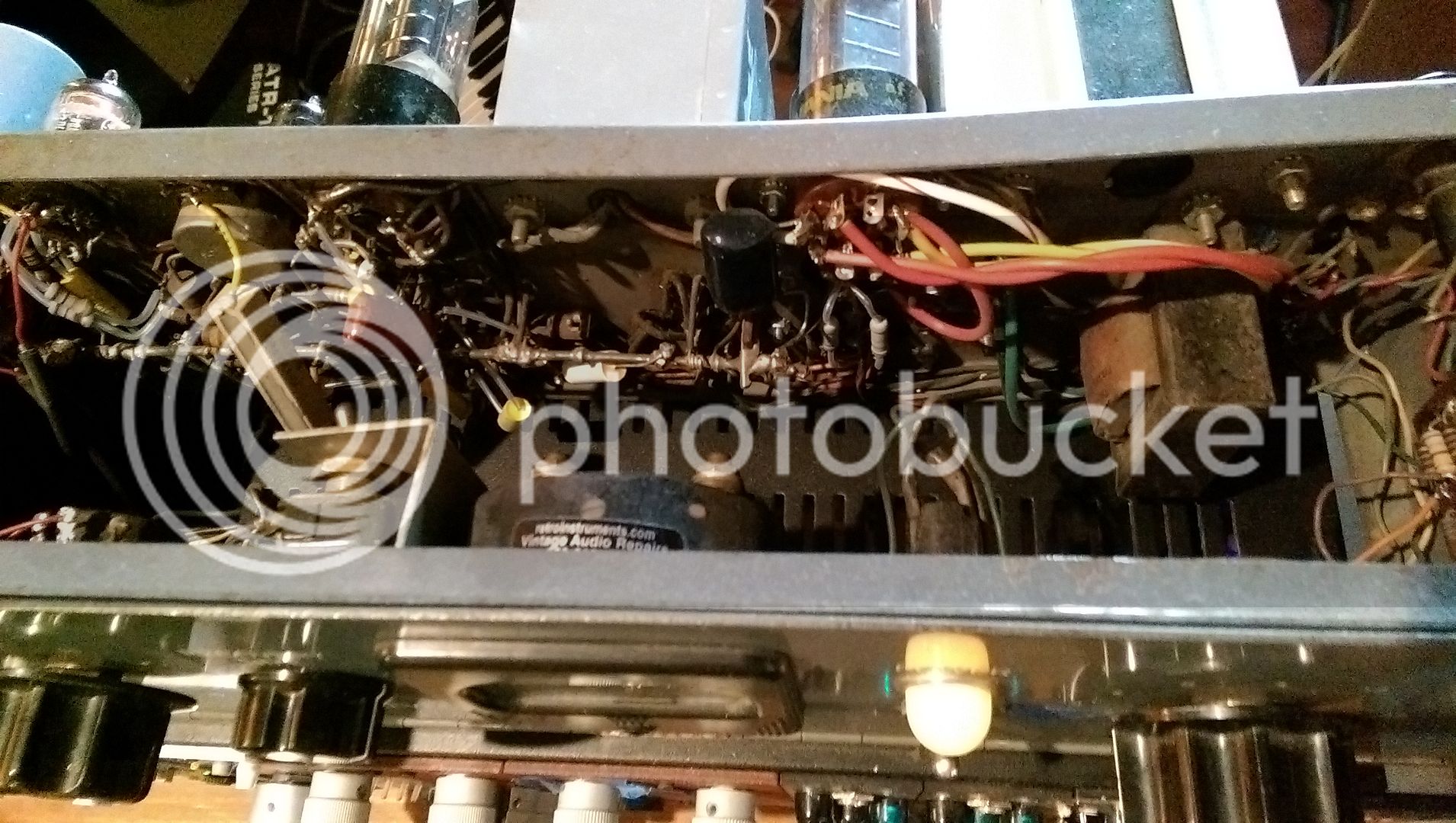
I would like to follow the original layout as closely as possible and I'm wondering if anyone has or can take some clear inside shots of the Sta Level.  I've managed to uncover a couple of inside shots, but they are not totally clear with respect to the layout around the input section, transformer, 6386 and 12AT7 as it is covered by the cabling to the input level control.

Also, I've noticed that the schematic includes a pad before the input transformer, but in the pictures I've seen I can't seem to find those 5 resistors. It looks like the input goes directly to the input transformer. Was this optional?

Any help or tips would be greatly appreciated.

Pics here
http://analogaudiorepair.com/category/repaired/

Regards,
Mark
 
The pad is/was optional.  I found my build to lack enough gain for my applications so I took the pad out.  The manual says, "Levels as high as +24dBm may be fed into the amplifier terminals..." "With the pad removed the maximum line input level is +4dmb and the gain level is increased approximately 20db".
I will be at a studio with an original in the next couple weeks and if their Sta-Level needs servicing (which is unlikely) I'll snap a few pics for you.  FWIW, I would not worry about copying the original layout if it's a matter of tone.  You can do a better layout and still nail the tone.  Some of them were pretty sloppy in terms of build.  I've heard many people say that they all sound different and the fact that they used different brands of components at various times would support this to a degree.  The Sta-Level is my all-time favorite piece of gear but having used an original, a Retro, and one built on a Drip PCB w/ a variety of new and vintage parts, I personally don't have interest in replicating the original's physical layout like I do in an LA-2A.  Best of luck, whatever direction you decide to go in.
 
Also, I've noticed that the schematic includes a pad before the input transformer, but in the pictures I've seen I can't seem to find those 5 resistors. It looks like the input goes directly to the input transformer. Was this optional?

Gates pads were often placed on large spacers (metal octagonal type) mounted on the side wall near the input or output.  They should be on a small square brown turret board. Unless you will have situations where you have to be feeding it signal that will overload the input transformer I would suggest omitting it.  They were removed or sometimes additional ones were added by radio station techs. 
 
Thanks Bowie

The layout doesn't look super challenging based on the few pictures I've seen.

I'd like to stick to the original for my first try and then see if there are improvements that can be made.

Would love to see the insides close up.

Bowie said:
I will be at a studio with an original in the next couple weeks and if their Sta-Level needs servicing (which is unlikely) I'll snap a few pics for you.  FWIW, I would not worry about copying the original layout if it's a matter of tone.  You can do a better layout and still nail the tone.  Some of them were pretty sloppy in terms of build.  I've heard many people say that they all sound different and the fact that they used different brands of components at various times would support this to a degree.
 
Biasrocks said:
Thanks Bowie

The layout doesn't look super challenging based on the few pictures I've seen.

I'd like to stick to the original for my first try and then see if there are improvements that can be made.

Would love to see the insides close up.

Bowie said:
I will be at a studio with an original in the next couple weeks and if their Sta-Level needs servicing (which is unlikely) I'll snap a few pics for you.  FWIW, I would not worry about copying the original layout if it's a matter of tone.  You can do a better layout and still nail the tone.  Some of them were pretty sloppy in terms of build.  I've heard many people say that they all sound different and the fact that they used different brands of components at various times would support this to a degree.
Shoot, I knew I was supposed to be snapping Sta-Level pics today but I forgot why.  Anyhow, I got a few but the light was bad and I don't think they'll be helpful but here's one pic.  As you can see, they can be a real rat's nest.  Retro serviced this one (new PT, few new caps, and added their mod).  I'm supposed to make a lid for this one so I'll get some pics in a couple weeks when I'm back at the studio.  BTW, there is a pad on the input of this one.  It's on the left panel (when facing the front).
This link might give you better rez and zoom;  http://s98.photobucket.com/user/slightlydazed7/media/IMAG2949_zpstthduidz.jpg.html
IMAG2949_zpstthduidz.jpg

 
I've built a few P2P sta levels & also repaired an original.  The original was a real PITA to repair, mainly because of the poor soldering iron access, but also the resistor/cap/wires are all wrapped around each other several times.    I found it pretty easy to make my own layout, to the point where I came up with a new layout for every one I made  In my view its easy & better to mke a layout where everything is accessible & easy for servicing etc.   

At the end of the day you make your choice, & live with it.
 
I built a PTP with a friend.  It sounds unreal.  We did our own layout and it is dead quite.  ( I sourced my tubes from Bowie)

Bowie, do you find you could use a pad on the output.  I feel like I always have to have my output pot all the way down.  I am thinking about changing it around a little to give it a more usable range.
 
dandeurloo said:
I built a PTP with a friend.  It sounds unreal.  We did our own layout and it is dead quite.  ( I sourced my tubes from Bowie)

Bowie, do you find you could use a pad on the output.  I feel like I always have to have my output pot all the way down.  I am thinking about changing it around a little to give it a more usable range.
Absolutely, almost mandatory.  Without the pad, I couldn't open the output pot (Mallory T-600) more than 15% max, but it was more like 10% on most material.  Some of the guys here helped me figure out a good pad without messing up the impedance (can't remember what value I used but I looked up the thread; http://groupdiy.com/index.php?topic=56485.msg720574#msg720574) and now I'm usually sitting around 40 to 60% open on the output, which is ideal.  Definitely go for the pad.
 
I couldn't open the output pot (Mallory T-600) more than 15% max

Was this a vintage one you just had in stock or tracked down on ebay?    State has them, but apparently has no interest in making them anymore.  I spoke with someone and requested a quote. Never heard anything.  Useless.  Probably have to order 1000 of them to get their interest.

http://www.potentiometers.com/SeriesTpad.cfm


For a fixed H-Pad, 220r series and 100r shunt works great.  Use 5W on the incoming legs. 2W is fine for the output side. 2W on the shunt. 
 
I never used any fancy T or H attenuators.  I removed  R28.  That way you can turn the output completely down & the whole pad is still balanced.  It worked very well.  3 of the sta levels I built are used in commercial studios in London & have never had issues with this mod.

It's useful to make R17 & R18 (82K) a couple of watts & metal film.  Originally I made these 1 Watt carbon film & they went high value after a couple of years & needed replacing.
 
lassoharp said:
I couldn't open the output pot (Mallory T-600) more than 15% max

Was this a vintage one you just had in stock or tracked down on ebay?   
Both, I happened to have one in my parts cabinet but it was one I had originally sourced on ebay.  Using a PEC pot just wasn't working out.
 
I think every one I've serviced still had the factory pad in it, and with the two pads in place it was more or less a unity -> 10dB device.  Worked fine with modern line level sources.  If anything, one needs more pad today than they did back then.    Parallel to this, every Collins 26U I've worked on ended up with a 20 dB input pad, otherwise the input attenuator was almost off at all times.  The input pads might get in the way if you want the thin slamming hard at all times.  Put it on a switch. 
 
I left the input pad on when I build it, I replaced the output control with a 3-deck, 12-position, (bridged-T) attenuator, which works really well. I've often been tempted to remove the input pad and use this comp as a mic pre. I think the STA is the loudest comp I have.

I agree with others in that this compressor is not too difficult a circuit to lay out. I found it relatively easy to come up with a turret board layout that worked well and was quiet.
 
Biasrocks:

If the layout is something you need for best  perfomance or is it just for "original" specs?

I have built an Altec-clone and for sure changed the layout completely because I placed it all inside a 1U rack chassis.

Thera are no hum or other issues from poor layout so maybe this could be of intrest?

Please let me kno and I will send you a pic of the interior.

Best regards

/John
 
Nice, thank you Rob.

It looks like a 1RU case with an extended 3RU front panel to make room for the tubes and transformers, is that right?

I'm thinking I'd like to have the tubes and transformers hanging off the back similar to the original.

Food for thought.

Mark
 
Nice work Rob. Do you mind me asking where you get those terminal strips ? are they like forked turrets ? Cheers
 
It looks like a 1RU case with an extended 3RU front panel to make room for the tubes and transformers, is that right?
Yes.  Sometimes I've done it the same way but in a vero rack.  I build a platform in it at about 1U height. Then it's easy to fit a gill/mesh


I'm thinking I'd like to have the tubes and transformers hanging off the back similar to the original.
It's a bit easier to protect them this way.
 
beatnik said:
Nice work Rob. Do you mind me asking where you get those terminal strips ? are they like forked turrets ? Cheers

I used to get them from a military surplus place that was quite close by to where I live.  They are individual 2way tags on ceramic stand offs.  Great for valve stuff because of the ceramic insulation.          I used to also get some great valves & oil filled parmeko mains transformers & chokes from the surplus place.  Also meters, pots caps everything & all the highest quality NOS parts.    I think the guy just sels on ebay now but I can't find him.  Sadly the prices are much more expensive now.
 

Latest posts

Back
Top