Console PSU using multiple OEM PSU's - correct wiring

GroupDIY Audio Forum

Help Support GroupDIY Audio Forum:

This site may earn a commission from merchant affiliate links, including eBay, Amazon, and others.

Krcwell

Well-known member
Joined
May 11, 2014
Messages
152
Location
US
Hello all,

I'm putting together a PSU fora 500 series console project.  After a good amount of reading, I've decided that pre-made OEM linear PSU's from International Power, Power One, etc... is the way to go.  I understand somewhat how to hook everything up, but am not confident enough to just try it out.  Any and all advice is greatly appreciated.

I'm using 2x 15v 6A International Power PSU's to provide the +/-16v rails:
http://www.galco.com/buy/International-Power/IHD15-6.0

1x 48v 0.5A for phantom:
http://www.galco.com/buy/International-Power/IHB48-0.5

and 1x 12v 1.7A for relays/logic:
http://www.galco.com/buy/International-Power/IHB12-1.7

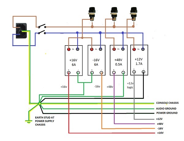
Here is the basic wiring diagram I have put together thus far:


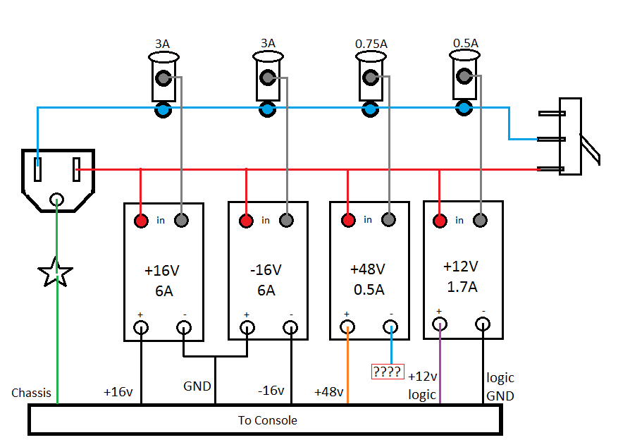
Do I have the wiring scheme correct?  I'm feeling kinda light on star ground connections.

I'm not quite sure what to do with the - side of the 48v PSU.  My first instinct is to run that to Star ground.  Actually, same thing with the +12v PSU.  Would that go to Star instead?

Once again, any and all advice is greatly appreciated.  Thanks!

Keith
 
OEM psu's have a floating output till you ground one side to give you + or - X amount of VDC  so you will need to run the - output on the phantom power supply to ground in order to get you you +48VDC for phantom.
 
pucho812 said:
OEM psu's have a floating output till you ground one side to give you + or - X amount of VDC  so you will need to run the - output on the phantom power supply to ground in order to get you you +48VDC for phantom.

Thanks! Audio ground or star point ground?
 
I'm not sure if I'm still missing a coffee, but I wouldn't turn that switch on, it makes a direct short between main line Phase and Neutral.

I would keep the red line out of the switch, just connected to the PSU's. The blue wire from the mains inlet should go to the switch, only to the switch, and the other contact of the switch to the fuses.
 
dirtyhanfri said:
I'm not sure if I'm still missing a coffee, but I wouldn't turn that switch on, it makes a direct short between main line Phase and Neutral.

I would keep the red line out of the switch, just connected to the PSU's. The blue wire from the mains inlet should go to the switch, only to the switch, and the other contact of the switch to the fuses.

I noticed this too, but then thought we are assuming its a DPDT switch.

But best we clear this up  ;D
 
Hi,

This switch should be a DPST On-Off style.

When you power the unit off, you want to cut live AND neutral. (just i case they're reversed) ,

Then, you can power all the units in parallel.

As for the grounds, i would run them separately to the console and route them to the same 'star point' at the PSU case. With 48V's references being wired to the console case.

But that's only  my 2 pence opinion, I might be wrong.

Thomas
 
dirtyhanfri said:
I'm not sure if I'm still missing a coffee, but I wouldn't turn that switch on, it makes a direct short between main line Phase and Neutral.

Humner said:
I noticed this too, but then thought we are assuming its a DPDT switch.

But best we clear this up  ;D

Thanks for the heads up!  I think the safest thing to assume is that I have no idea what I'm doing.  I've built a couple of kit PSU's before, but those also included robust instructions.

I've updated the wiring diagram for the switch layout Totoxraymond suggested, as it seems the most "safe".  Does this look better?


In regards to the grounds:

totoxraymond said:
As for the grounds, i would run them separately to the console and route them to the same 'star point' at the PSU case. With 48V's references being wired to the console case.

Thomas

Does the above updated picture reflect what you are saying?  Would I also want to run the center tap of the +/-16v to star ground as well?

Thanks again to everyone for the help.  I really appreciate it!

Keith


Krcwell said:
I've updated the wiring diagram for the switch layout Totoxraymond suggested, as it seems the most "safe".  Does this look better?

Well, this way, you won't put fire anywhere. And you won't be risk any electrocution while troubleshooting things and you forget to unplug everything.


Krcwell said:
Does the above updated picture reflect what you are saying?  Would I also want to run the center tap of the +/-16v to star ground as well?

Thanks again to everyone for the help.  I really appreciate it!

Keith

Seems good to me, I would run transformer's center tap to ground since it's the reference from AC voltage. But once again, someone may prove me wrong. 

Thomas
 
On 500 standard there are two grounds. Audio and Power both of which are tied to earth chassis stud at power supply.

I would also use a single mains fuse for the + - 16V rails.

500_Console_PSU.jpg
 
Thanks Sahib! It makes way more sense now.

Would the shared fuse for +/- 16v supplies still be 3 amp?
 
You are welcome.

The fuse should be rated at the combined power consumption of both PSUs.  As yours will be 120V mains operated you are looking into 1.6A. With a bit of margin 2A would be sufficient.
 
I would connect the AC power Safety Ground to the chassis near the power inlet connection. Not the Star Ground.
I would connect the +48 V DC Neg to the XLR pin #1's of the mic input connectors.
I would connect the Star Ground to the chassis near the input connectors.
 
I like to connect the phantom ground to wherever it fits (star point for example), low current so not usually a problem. What I do is to add a RC filter from where I connect the 6k8 resistors (~330Ω 220µF maybe? 20db filtering at 20Hz and rising). The (-) of the cap directly to pin 1 of the XLR so the phantom is tied to it.

JS
 
totoxraymond said:
As for the grounds, i would run them separately to the console and route them to the same 'star point' at the PSU case.
I wouldn't do that.
It seems everybody is so obsessed with star ground, they loose sight of the overall picture. Joining the 0v references at the safety earth AND somewhere else in the device results in ground loops.
The audio 0v is meant to be floating until connected to chassis ground at the backplane.
The Ov of the 12V supply is alsio meant to be floating. Failure to do so would allow the switching currents to be shared with the audio "ground".
The original arrangement (with the negative of the 48V being either run separate or connected to chassis earth) is a much better choice.
 

Latest posts

Back
Top