Soundcraft EQ Mod ?

GroupDIY Audio Forum

Help Support GroupDIY Audio Forum:

This site may earn a commission from merchant affiliate links, including eBay, Amazon, and others.

rrs

Well-known member
Joined
May 28, 2005
Messages
519
Location
Wagga Wagga - NSW,Australia
Hi

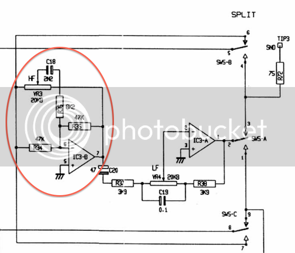
I have a Soundcraft Spirit Monitor console that I modded early this year and sounds quite good, even the EQ. Basically just replaced components, OpAmps and Powersupply.

But I really would like the fixed Hi Shelf EQ to be adjustable.

Anyone know how to go about this ?

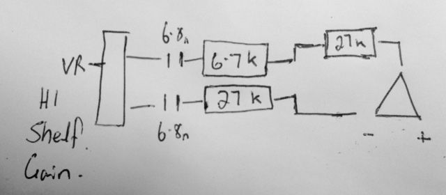
Here is what I seem to have currently,

Spirit%20HI%20Shelf.jpg
 
How much space do you have? A switch to change cap values is the most straight forward for a shelving EQ.

If you want continuously variable with a pot it's more complicated including additional components and opamps
 
rrs said:
Thanks John.
The frequencies ideal would be around 5k, 8k and 12k

How would i acheive this given what I currently have in the diagram above ?

Do you have the actual schematic, or could you draw out the complete HF stage? Having two caps is a little unusual for the typical shelving circuit in these types of consoles.
 
Screen%20Shot%202016-09-24%20at%2010.22.11%20AM.png


OK so here,s for the Spirit Studio , seems identical apart from the extra capacitor in the Monitor version between the VR3 and R34 as well as values the 2 X 27R is 47R here and seems to mirror the other differences. I have no idea how to do a proper schematic but apart from the different values makes sense.
 
rrs said:
.. seems identical apart from the extra capacitor in the Monitor version between the VR3 and R34 as well as values the 2 X 27R is 47R here and seems to mirror the other differences.
You'll have to explain or show a bit more.  There are no 27R s or 47R s in that pic.  :eek:
 
rrs said:
OK so here,s for the Spirit Studio , seems identical apart from the extra capacitor in the Monitor version between the VR3 and R34 as well as values the 2 X 27R is 47R here and seems to mirror the other differences. I have no idea how to do a proper schematic but apart from the different values makes sense.

That is more typical of what you usually see. You can vary the frequency by changing the value of C18, you would need to find the equivalent in your console and confirm the topography is the same.  Adding something like an On-Off-On 3 way toggle switch with appropriate caps would do the job.

Also I think you meant 2 x 27k and 47k not 27R 47R.
 
Ok thanks that sounds good.

Is there a place a can work out what I need or formula to do this.

Also I saw the Gyraf Calrec schematic looks very similar but there is a VR where the smaller value resistor is (R36) . I just tried that and my first impression is that it woks. Does this sound right ??
 
rrs said:
Is there a place a can work out what I need or formula to do this.

Google "rc filter calculator" and put in values with the 2n2 and adjust R until it gives you the correct current corner frequency (12k?). Now you have a model of what you have now. Then play with C until it gives you the desired frequencies.

Note that with a center-off toggle, the lower frequencies are going to be made with caps in parallel so find another online calculator to figure that out.

The relation is very simple: f = 1/2*pi*R*C. So if you double the capacitor you halve the frequency.
 
squarewave said:
The relation is very simple: f = 1/2*pi*R*C.
but is missing the brackets (resulting in a factor 575,922,870 difference for the 2n2/6k029 parts values for 12kHz).
use f= 1 / ( 2*pi*R*C ) instead, with pi=3.14159..., R in ohms and C in Farad
 
I think the easiest way to determine things is to use a free spice simulator.

Changing R36 changes the frequency but it will also change the gain and response. It's real purpose is to set the limit of the overall response and +/- gain of the circuit.  Though you can vary it if it fits your needs.

If you choose to change C18 then you can estimate with a simple inverse relationship. Double C and frequency goes down by half, and so on.
 
Oh one think also is there is a capacitor between VR3 and R34 the same value as well. Would that be changed to the same value ??

Also why would this cap be there ?

Is there also a way to adjust the slope ?

Sorry for all the questions :)
 
rrs said:
Oh one think also is there is a capacitor between VR3 and R34 the same value as well. Would that be changed to the same value ??

Also why would this cap be there ?

Is there also a way to adjust the slope ?
Do you mean there is a very small capacitor (<100p) between the op amp output and inverting input? No, that is a stabilization capacitor that has nothing to do with the filter.

The slope is set by the number of poles which in this case is fixed at 1. Making it steeper would require more poles and thus more capacitors (or inductors) and a significantly more complex circuit.
 
Back
Top