LA2A and T4B

GroupDIY Audio Forum

Help Support GroupDIY Audio Forum:

This site may earn a commission from merchant affiliate links, including eBay, Amazon, and others.

chriss

Well-known member
Joined
Jun 14, 2004
Messages
386
Location
Potsdam, Germany
Hello,

I am currently doing a bit of 'research' on the LA2A and the T4B. Since I know I'm not alone in this I try to discuss some things here:

1.)

There seem to be different versions of T4A / T4B:
The Audio-Cyclopedia-circuit shows only one LDR between pin 7 and 8 the circuit of the LA3A and LA2A show two LDR's in parallel here.
Pins 5 and 6 are the same in all circuits. Since this is used for metering only it seems to be of less interest anyway.
Between pins 2 and 3 there is the EL-foil in all the circuits but in the T4A there is a resistor between 3 and 4. In the T4B there seems to be another LDR in parallel to the EL-foil.
Since I have never seen this LDR in any of the projects here on the forum I wonder what do you guys think about that?
And the three circuits show there should be T4's with 2, with 3 and with 4 LDR's?!... All the clones I have seen here only use 2 LDR's.
Any opinions about this?

2.)

Does anyone know a source for the LDR's in Germany or otherwhere in Europe?

3.)

The LA2A uses 12AX7 and 12BH7 for the gain-make-up-stage. The 12AX7 could be replaced with ECC83 but what about the 12BH7, is there a more common tube or a tube more spread in Europe that it could be replaced with? ECC88, ECC808, maybe?
What is the function of the 12BH7 anyway? Is this a phase-invertor? Would that make sense in this circiut? I don't know very much about tube-technology but I think I understood that the phase-invertor is needed to create a symmetrical signal for the power-amp tubes. But for driving an autput transformer is this necessary? Maybe it's not a phase-invertor, I'm sure you can tell me!
Or maybe there is a complete replacement-circuit for this amp? How much dB does it make up anyway? 34? So I could just take a V72. (just kidding...)

4.)

Can anyone tell the max. AC at the EL-foil that LA3 or LA2 put out? Just to have a ballpark to where I have to get the amplification...

5.)

Is there any idea what the transformer for EL-foil in the LA3A could be replaced with? I have done some tests with different ones connected to my Freq.generator. The only one that made the EL shine was an reverse-connected power-transformer that only worked around 400Hz. I have tried a 1:10 Audio-transformer that didn't work. Maybe the output of the generator is not high enough. I will try two of the 1:10's in parallel today and maybe another F/G.
Does anyone know the amplification that the discrete amp in the LA3A puts out?

So this is it for the beginning. I hope interesting feedback to come ahead...

thanks

Chris
 
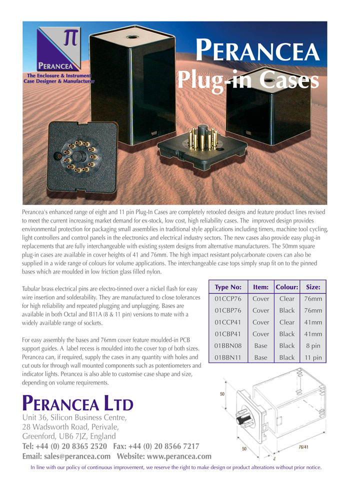
I found a thread where scenaria mentioned there are no octal-socket-housings available. Well - he's wrong:

plugincases.jpg


RS components sell them

Chris
 
[quote author="chriss"]The LA2A uses 12AX7 and 12BH7 for the gain-make-up-stage. The 12AX7 could be replaced with ECC83 but what about the 12BH7, is there a more common tube or a tube more spread in Europe that it could be replaced with? ECC88, ECC808, maybe?
Chris[/quote]
12bh7 - Uk stockist - many varieties
http://www.watfordvalves.com/newoldstock.htm
According to them - it is the driver in the Ameg SVT Bass Amp
 
[quote author="chriss"]I found a thread where scenaria mentioned there are no octal-socket-housings available. Well - he's wrong[/quote]
Hmmmm... That's a little confrontational dontcha think?

Certainly, those octals that you;re looking at are MUCH bigger (wider, fatter) than the T4 can. You can buy plastic octal relays by the dozen locally, but they're NOT T4 cans. Thay can be used as T4 cans if you like, but the T4 can was skinny, metal and elegant. Relay sockets are wider, clunkier and not so nice looking, whereas the Perancia cases are even more clunky looking...

Keith
 
I have a source in the U.S. that supplies 4 sizes of cans. I think I saw one that was similar to the T4B.

But does size really matter?

Also isn't the original EL strip from LSI spec's at 400khz?
Military aircraft runs at 400khz power I believe (if I remember well from the time I was in military supply).

Jim
 
sorry keith,

i didn't want to hurt your feelings. and i thought the T4B-can HAD a relais-socket.

sorry screnaria,

there is so much stuff on the LA2A and T4B that I use to read a bit too fast sometimes... I didn't get that you were talking about the original housings.

i wouldn't care to much about that fact for my own project. i don't think the metal is necessary, since shielding doesn't matter on the T4, does it? and if metal cans are not available and plastic cans are, it's o.k. for me to take them.

bluzzi,

i was talking about 400 Hz not 400 kHz. but anyway the foil should work from 20 to 20000 hz in the t4b since the audio is only amplified and then fed to the el-foil. in think that it worked with 400 hz was because of the power-transformer that i used. it probably works as a kind of bandpass-filter.

and uk03878,

thanks for the link. i didn't know sovtech produce them! and - yes i remeber the 12bh7 was one of more than 20 (!!!) tubes i had to exchange in my old ampeg svt once... one should replace the font-cover of the svt against plexi-glass so it works as a display-cabinet...

chris
 
Chris, everything your after has been beaten too death at this forum and the previous two versions behind us.

So do some searching, like the "All Things LA2a thread".

As far as the T4, that's been beaten to death also.

You might find some info here:

http://www.vacuumbrain.com/

cj
 
Oops! I meant 400hz! Not 400khz! Sorry.

If you are looking at building your own T4B or creating a new one keep me in touch. I want to do that but not for the moment. Have to finish my LA2A first. I just got some old Weston meters and all I can say is WOW! I also got some newer VU meters and they just don't compare. These things look like they were made by a Swiss watchmaker.


Jim
 
CJ,

you are right, there is some info that found after I wrote the thread. But not all.

I couldn't find anything about: " Why are there no T4Bs with 3 or 4 LDRs like the schematics show them? "

Yes I found the voltages in a LA3A at max. G.R. somewhere: "70vac at 20Hz, 46vac at 1000Hz, 122vac at 20kHz. With the HF contour set full the gain reduction peaks at 8K, then tapers off from 8khz to 16khz."

And o.k. I can still buy 12BH7 but I'd like to understand the schematics anyway and I didn't find descriptions of this as well.

And regarding the LA3A-transformer-question: Jürgen Haible asked for that before as well and it wasn't answered really. I'm just curious how that could be done.

Jim,

I started with experiments on the T4 first since I had this EL-foil lying around and I found it funny trying to make that thing light as audio is fed in. So I will start with the sidechain-section first. And I want to do this part the solid-state way like in the LA3A. I can keep the forum informed if this is of any interest.
I don't want to annoy since the subject "building my LA2A" is really not rare in the forum. But I don't want an exact clone I want an "LA23".... And I don't have all the informations I need yet.

regards

Chris
 
A little OT: Don't forget-the 6V6 is a better choice than the 6AQ5. Much better mechanics, much easier tube socket to wire (big octal vs puny 7 pin).

Electrical characteristics the same, and a little more common than the aq5.

cj
 
Hi CJ,

thanks for the additional info.

But first: What does "OT" mean? (don't forget: I'm from germany...)

And second: That's the point I want to avoid in my idea of a "LA23": My idea is to have the gain-makeup-stage in tubes and the control-path in solid-state. I doubt very much that one can hear a difference between the EL-foil being driven by tubes or transistors, so I think here the driver-section of the LA3A is what I prefer. I feel if I'd use tubes here it would be a waste of electrical energy, space and rare and expensive parts in a place where it just has to fulfill a very simple electrical task that is away from the audio-path. Does anyone here think tubes are the better EL-drivers? And if so, why? I'm not teasing, I'm really curious.

I understood the circuit of the LA2A and LA3A like this:
- The input signal is drawn more ore less to ground via a LDR depending on the brightness of the EL-foil.
- The output-gain is amplified by a tube- (LA2A) or transistor- (LA3A) -stage to make-up the loss of gain.
- The brightness of the EL-foil is controlled with a small power-amplifier that is to amplify the 1,23 Volts to ~80 Volts to drive the EL-foil. In the LA2A done with a tube-stage (12AX7 and 6AQ5) and in the LA3A done with a transistor-amplifier followed by a transistor.

Did I get anything wrong here? I'm really not into teaching or preaching anything, I just try to understand all the stuff I am about to do. And I like even tube-circuits to be as most modern as possible...

I hope I didn't bother anyone again, since I want use this forum for information-exchange and not for penis-comparison. I really like the way information is shared here and I always try to do my best to share my little knowledge as well, even if some guys might find me annoying...
Maybe it's the language-barrier...

Chris
 
Ahh, danke Darius!

I have done some more 'scientific research':

Since I did't know if the not very impressing-looking 1:10-transformers I bought would do the 'drive-El-foil-job' I just connected the transformer to the Speaker-out of my HiFi-Amp and the EL to the other side of the transformer. And yes, it worked and looked very interesting. But I had to turn the amp very, very loud. Maybe I should try the same with two 1:10s in parallel again. Btw.: It was Nancy Sinatra's 'These boots are made for walking' on the radio if this of any interest...

Chris
 
Penis comparison that did make me laugh :grin: I sometimes feel a bit funny too with some of my questions as my knowledge level is a bit sparse, but everyone has been great so keep asking questions others like me also benifit,
anyway I was looking at the LA3A schematic for the 1st time, it looks more hasstle than the plain tube version to me like you said it needs that transformer, what about power supply? with the tube version your gonna have a power supply anyway, as CJ said 6V6 {instead of 6AQ5A} easey & cheap to get, same for 12AX7/ECC83.

Anyway best of luck whatever way you do it.

Cheers ...............Gary O.
 
thank you gary. but you still have the advantage of being a native speaker...

yes the LA3A power-supply: I don't know the two voltages it puts out. but I doubt that it makes a bif difference if it is 24 or 30 volts?!.. and for the tubes i'd need a supply for 6,3 V anyway, so i could go 24->6,3 and 24->200 volt for te anode. btw.: how high should this voltage be exactly? i think that was mentioned in another thread i found yesterday. so it's a few transformers anyway. i didn't find tube-transformers that are small enough, most are for power-amps and i find that too large.

i know it may sound weird to combine the transistor and tube-versions. i will see want i will end up with...

regards

chris
 
EL drive voltage probably peaks out at around 120-140 VAC, so yes, yoü need a step up x-former unless yoü use high voltage transistors.

There are other things in the side chain like pre-emphasis caps, stereo link, and what~not, but I think you could do away with them.
 
Hey CJ, how did you do that german Ü? Copy and Paste?

And yes my first test with the tiny 1:10-transformer worked not so good and after a while I relized it became very - well warm... Another while later - ahh let's not talk about this transformer any longer... I bought an 100V-transformer and this seems to work much better. I tried it with 'The White Stripes' this time.
In the LA3A-schematics I was wondering about the values .31 - 2.5 and 5 on the EL-transformer. And now my 100V-transformer says 0,625 - 2,5 - 5 - 10 and 0 on the secondary site. Watts is what it means here and I assume so it does on the LA3A-transformer?!. Would mean that they DID use a 100V-transformer, wouldn't it?

CJ, the pre-emphais-cap: Do you mean C7? Am i right that this thing is a simple power-amplifier with not so much power-output?

I wonder if maybe a simple EQ in the sidechain rather than this high-f-preemphasis would be a good idea. A number of compressors have this feature but I have never used one so I wonder if the LA2 would benefit from this...

Chris
 
I done a experiment with my LA, I made a very simple ic amp/LED driver 1 IC just a few extra bits run from 12 volts replaced the EL circuit with this & worked a treat it seems to me the LDR & make up amp is the essence of the LA2A.
 

Latest posts

Back
Top