Audio test set

GroupDIY Audio Forum

Help Support GroupDIY Audio Forum:

This site may earn a commission from merchant affiliate links, including eBay, Amazon, and others.
This is the catch-22 for designing test equipment... What do you plan to measure with it? If you want to tweak out performance of a THAT 1646 you need a path significantly better.

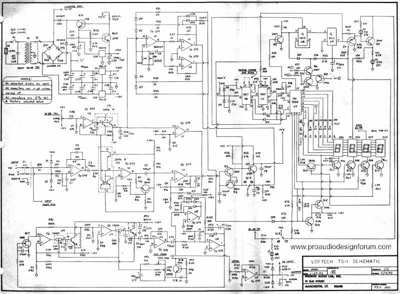
Back in the '80s when I designed a practical Audio range test set for trouble shooting I accepted less than bench level performance to keep costs down. The product was successful because when you troubleshoot gear it usually misbehaves pretty grossly (and a lot of equipment back then was not as flat and linear as today, like old tape recorders).

These days you could cover my old unit with a sound card... To get significantly better than a sound card takes some effort. Perhaps that might be a direction to pursue. Hot rod a sound card to extend the resolution/noise floor/whatever.

That way the available software to repurpose sound cards could be utilized.....  or not.

For example to extend the measurement range for using a computer sound card to measure noise floor, build in a SOTA front end gain stage, maybe with noise weighting built into the front end gain stage. That way the sound card noise floor is effectively scaled down by the gain stage and now limited by that gain stage noise floor.

As Sam has documented with some of his exploration of test equipment design limits, you always run into some threshold. So pick your poison.

JR

PS: Decades ago to extend the measurement range of my (budget) test bench I used a heathkit distortion analyzer in front of an old used spectrum analyzer. Neither unit by itself was very remarkable, but together I picked up a couple ten dB of more range. FWIW I had to run the Heathkit audio path at -10dB from nominal zero, for the heathkit's own distortion to not dominate my distortion measurement floor.


JohnRoberts said:
This is the catch-22 for designing test equipment... What do you plan to measure with it? If you want to tweak out performance of a THAT 1646 you need a path significantly better.

What I would plan to measure with it would be the sort of gear we design/build here.

Cheers

Ian
 
I have been looking at sound cards today and it seems that this path is a possible option indeed. I looked at:
- Prism lyra - very nice but probably to pricey.
- Lynx Studio has a beautiful Hilo AD/DA...
Dante DSP like the new Symetrix Edge units. Dante would be cool, but unfortunately no linux support yet.
dspecialists aubion - cool, but no linux support either, and pricey

the front end would really make the difference. an other option would be to use a pimped frontend on something like Uwe Beis AD and DA boards and then straight into a digital I/O.
the I2S interface on the Raspberry Pi seems not fully functional right now, I haven't seen any success story - specially no input for the moment. otherwise this would still be a nice option. I would want to keep a onboard sine gen to check absolute levels and make sure there is no system software messing with them, otherwise its just an other RMAA thing.

In the office we have a duran audio interface. that it uses USB but doesn't send audio through the Windows Audio subsystem but through a proprietary driver. that makes repeatable measurements easier. no linux support either. I didn't test it regarding low THD but I will give it a go eventually, just to see how it performs.

I think I might build uwe beis AD/DA boards an test them..... may be with modified gain ranges / attenuator - seems a viable option for most of my uses.

- Michael

 
I have given this more than a little thought... and I also have some experience as I designed the Loftech TS-1 back in the '80s which had a sine wave, DB meter, and frequency counter in one unit.

I have resisted the strong temptation to design a modern version, but if I did here are a few thoughts.

#1- I would absolutely use a digital micro as the heart of the system.
#2- Why use a function generator chip.? You can program a look up table into the micro and output to a DAC (Microchip has 2x 16b DACs built into one recent DSPic family).
#3- I haven't looked at using the 2252 as a meter front end. Back in the '80s I made my own log conversion using a cheap transistor array. It might take 2x 2252 to generate the 0dB reference and temperature compensate? There are accuracy issues with analog conversion that a pure digital approach should be able to get around. Note: Back in the '70s(?) DBX made a slick stand alone dB meter.
#4-cheap PICs have as much as 12 bit A/D, while 16b+ external A/D can be had for $1 or so. You can further expand the measurement range with the equivalent of smart front end auto-ranging. If the micro brain knows it is measuring a small voltage it can add low noise voltage gain in front of that extending the low end of the measurement range. For measuring high voltages a smart pad.

Pretty much every thing about my old TS-1 could be improved and done for lower cost using modern technology but, there are so many cheap alternate solutions that I can't get very excited about going there.

JR
Here is discrete rms-log
RMS.gif

here is whole TS-1
Loftec_TS1.jpg

larger images here
Loftech TS-1 Schematics - Pro Audio Design Forum
Warning lots of unconventional circuitry in my old TS-1... enjoy.
The TS-1 has long been my favorite. Very low distortion ( good enough that I can set amp bias by listening for crossover distortion at very low level with headphones), full range frequency available with no band switching ( essential for finding buzzes in cabinets), clever impedance measurement built in, and a joy to use. The accompanying book is fabulous too! I wonder if you would ever favor us with a design theory write up for the oscillator portion? Thanks!
 
The TS-1 has long been my favorite. Very low distortion ( good enough that I can set amp bias by listening for crossover distortion at very low level with headphones), full range frequency available with no band switching ( essential for finding buzzes in cabinets), clever impedance measurement built in, and a joy to use. The accompanying book is fabulous too! I wonder if you would ever favor us with a design theory write up for the oscillator portion? Thanks!
Loftec_TS1.jpg


I'll begin with a brief overview... the design task was to make a voltage controlled sine wave generator clean enough for general troubleshooting, that could sweep from adequately below to above human hearing, and cover the generally accepted audio passbands (20-20kHz) with one knob.

The sine wave oscillator is in the bottom left corner of the shared schematic. The voltage control is provided by a 13600 dual OTA (operational transconductance amplifier). OTA are actually current controlled. The frequency pot voltage is converted to a current by a 6.2k resistor feeding into the OTA current mirror input port. This is easy enough for managing the HF end of the frequency range. The low frequency end is the hard part and you will see some extra glue circuitry around the frequency pot. Instead of connecting the LF end of the frequency pot to minus supply (which would cut current completely off) the LF end of the pot is connected to a transistor buffer approximating the current port input. Then an additional trimpot path sets the LF extreme (I don't recall but factory trim was probably set for 10-15Hz). Without the trim I could not insure reliable LF start up. 0Hz DC is not a sine wave, and unacceptable for bench use.

The next challenge was temperature stability. Running the OTA with a more than 1000:1 operating current ratio, can heat the device and cause temperature drift (also unacceptable for bench equipment). While not perfect I got it reasonable by letting the OTA PS rails sag to reduce thermal heat build up.

The oscillator topology is a conventional SVF (state variable filter). The JFET at the far left is the AGC amplitude control. Immediately to the right of the SVF is an inverting gain stage to get the output level stronger. Then two op amps perform full wave rectification of the sine wave output and compare that to a DC amplitude target. The precision rectifier diodes are biased on to reduce HF errors. A final inverting output stage boosts the sine up to full level.

There were many hours spent tweaking this. I could have made it lower distortion but at the cost of longer amplitude settling times and you don't want the level jumping around and overshooting when driving a loudspeaker to listen for rubs.

For extra credit look at the rest of that design. There is a lot going on.

JR
 
Wow !! Thanks so much John ! Lots for me to chew on here but your description certainly makes the schematic easier to understand. I am more familiar with OTB ( Off track Betting) than OTA but I will brush up. Thanks again! Rob
 

Latest posts

Back
Top