My bad, I was using AC voltage setting, however of course the output has been rectified to DC - when using DC setting I could calibrate fine with the dummy loads, now time to hook up the mic!I have built the PSU and have one other question around the voltages I'm getting. Can anyone help?
Firstly the 230v toroidal transformer is giving 270v at the output (I measured the input to be 240v - I based in the UK so this makes sense) - It's wired correctly in series and so I would expect roughly 240v at output - has anyone had this issue before - it mentions 12% regulation but 270 is right at the end of that - should I just replace for another one? Is there anything else in the circuit that could increase the voltage differential? 180k dummy load connected across B+.
I am getting a healthy 20v input and at the H+ rail output I'm getting 10v with 20hm res dummy load connected - this is as far as I can adjust it - I had hoped to hit the 5.3v mark. Any ideas these?
Is it worth placing a dummy load where the relay voltage would go?
Many thanks!
Silas
You are using an out of date browser. It may not display this or other websites correctly.
You should upgrade or use an alternative browser.
You should upgrade or use an alternative browser.
D-EF47 Tribute To Oliver Archut U47 Build Thread.
- Thread starter poctop
- Start date


Help Support GroupDIY Audio Forum:
This site may earn a commission from merchant affiliate
links, including eBay, Amazon, and others.
Hey all, I just rebuilt my D-EF47 psu today. I had to build a whole new one because I lost all my supplies in a fire a few years ago.
Anyway, Built up the supply and it all seemed to be fine. Trimmed H+ to 5.05vdc and was stable... Trimmed 105vdc at B+ but then when i switched to cardioid mode the B+ dropped to 85v. Maybe I wired something wrong with the relay/pattern switch? I went from COM to the common pin on the rotary switch, CRD to one side and OM to the other side... Pin 6 of the molex is going to pin 6 of binder connector and up to pattern pad on mic pcb. I can hear the relay switch and I hear the back capsule go null. I do hear a substantial POP in audio when I switch patterns.
I have the 24v relay in there iirc. And the appropriate relay coil resistor (14.3k ohms) installed on the PSU PCB.
Can any one think of why this would be happening with the B+ voltage?? Is this just the 24v relay sucking the voltage out of the B+ line? Did I wire it incorrectly?
Any help would be greatly appreciated.
Thank you")
Anyway, Built up the supply and it all seemed to be fine. Trimmed H+ to 5.05vdc and was stable... Trimmed 105vdc at B+ but then when i switched to cardioid mode the B+ dropped to 85v. Maybe I wired something wrong with the relay/pattern switch? I went from COM to the common pin on the rotary switch, CRD to one side and OM to the other side... Pin 6 of the molex is going to pin 6 of binder connector and up to pattern pad on mic pcb. I can hear the relay switch and I hear the back capsule go null. I do hear a substantial POP in audio when I switch patterns.
I have the 24v relay in there iirc. And the appropriate relay coil resistor (14.3k ohms) installed on the PSU PCB.
Can any one think of why this would be happening with the B+ voltage?? Is this just the 24v relay sucking the voltage out of the B+ line? Did I wire it incorrectly?
Any help would be greatly appreciated.
Thank you
Attachments


Is my mic safe to use?My microphone seems to work well right now but I measure a small voltage, about -35mv between cable ground and mic body, as well as a resistance of -22ohm. I can touch it without getting shocked but I am sure that I am doing something wrong here. Maybe the negative resistance and voltage could give clues as to what is wrong. When I turn off the psu, I measure about 1ohm in resistance.
When you say "cable ground" where are you measuring? And what part of the mic body are you measuring to? Does it have any kind of finish?Is my mic safe to use?
Do you have a load resistor tied from B+ to ground, equivalent of your relay coil plus current reducing resistor, on your opposite switch contact?Hey all, I just rebuilt my D-EF47 psu today. I had to build a whole new one because I lost all my supplies in a fire a few years ago.
Anyway, Built up the supply and it all seemed to be fine. Trimmed H+ to 5.05vdc and was stable... Trimmed 105vdc at B+ but then when i switched to cardioid mode the B+ dropped to 85v. Maybe I wired something wrong with the relay/pattern switch? I went from COM to the common pin on the rotary switch, CRD to one side and OM to the other side... Pin 6 of the molex is going to pin 6 of binder connector and up to pattern pad on mic pcb. I can hear the relay switch and I hear the back capsule go null. I do hear a substantial POP in audio when I switch patterns.
I have the 24v relay in there iirc. And the appropriate relay coil resistor (14.3k ohms) installed on the PSU PCB.
Can any one think of why this would be happening with the B+ voltage?? Is this just the 24v relay sucking the voltage out of the B+ line? Did I wire it incorrectly?
Any help would be greatly appreciated.
Thank you
Do you have a resistor in series with your 24V coil?
So, do I need to add a P2P resistor to the switch at all? Or that current limiting resistor is in the microphone? I followed all the schematics that Poctop laid out for us. As there were no build guides I just did it by heart.Do you have a load resistor tied from B+ to ground, equivalent of your relay coil plus current reducing resistor, on your opposite switch contact?
Turns out i recalled incorrectly about what voltage my relay was.. (built the mic in 2017) I looked it up by part number and its a 48V relay! Swapped out the Resistor on the PSU and now the difference between the voltages is only about 3v rather than 20v. So now in Cardioid (used 90% of the time) the B+ is trimmed to 105v and when omni is engaged it jumps to around 108v. Acceptable in my book.Do you have a resistor in series with your 24V coil?
Thanks for the help Delta Sigma.
Yes different relays needs different load resistor values, and some simple zener protection should be added as the relay is a fixed resistance in the B+ circuit,but when the relay coil broke the b+ voltage goes up to 200v which might ruin your capsule...So, do I need to add a P2P resistor to the switch at all? Or that current limiting resistor is in the microphone? I followed all the schematics that Poctop laid out for us. As there were no build guides I just did it by heart.
Turns out i recalled incorrectly about what voltage my relay was.. (built the mic in 2017) I looked it up by part number and its a 48V relay! Swapped out the Resistor on the PSU and now the difference between the voltages is only about 3v rather than 20v. So now in Cardioid (used 90% of the time) the B+ is trimmed to 105v and when omni is engaged it jumps to around 108v. Acceptable in my book.
Thanks for the help Delta Sigma.
The body of the XLR, which is physically connected to shield and ground of the cable, and the mic body tube, which I think has some sort of metallic paint, though I am not certain. I have also measured directly at the internal mounting rails, same results.When you say "cable ground" where are you measuring? And what part of the mic body are you measuring to? Does it have any kind of finish?
Interesting... Is the load resistor in the PSU or in the microphone? I dont have any resistors around the relay inside the microphone ... but there is a diode.Yes different relays needs different load resistor values, and some simple zener protection should be added as the relay is a fixed resistance in the B+ circuit,but when the relay coil broke the b+ voltage goes up to 200v which might ruin your capsule...

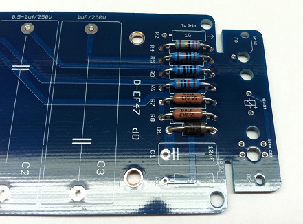
This is what I have in the PSU, the Rcoil relay R9 is the appropriate value for the 48v relay... do i need more than this to keep my microphone capsule safe?

Could I have damaged the capsule from having the wrong rcoil value in there before? When the B+ voltage was jumping up to 124v? I am noticing that the output of this microphone is a lot less sensitive than my u67. Its a genuine neumann k47 so i would be crushed if I messed it up.
Also, could/should I add a capacitor to front and back of capsule to tame the crazy pop that happens when the relay clicks over? I saw this on Oliver's m49 schematic...C1 is 1000pf. I now wonder if it was for this application as my m49 mic does not pop like crazy when the back capsule gets taken out.

Last edited:
-Load resistor is in the PSU (R5 14k for 48v relay) to provide a fix current/voltsge for the reed relay.(reed relay is Always powered on) The pop happens to the B+ line,it would need a new design to separate from B+ Line, means a third secondary transformer output,separate graetz,caps etc there is no space for that on this psu board.Interesting... Is the load resistor in the PSU or in the microphone? I dont have any resistors around the relay inside the microphone ... but there is a diode.
View attachment 100910
This is what I have in the PSU, the Rcoil relay R9 is the appropriate value for the 48v relay... do i need more than this to keep my microphone capsule safe?
View attachment 100911
Could I have damaged the capsule from having the wrong rcoil value in there before? When the B+ voltage was jumping up to 124v? I am noticing that the output of this microphone is a lot less sensitive than my u67. Its a genuine neumann k47 so i would be crushed if I messed it up.
Also, could/should I add a capacitor to front and back of capsule to tame the crazy pop that happens when the relay clicks over? I saw this on Oliver's m49 schematic...C1 is 1000pf. I now wonder if it was for this application as my m49 mic does not pop like crazy when the back capsule gets taken out.
View attachment 100912
-1000pf is only for the DC capsule isolation, you cannot DC isolate the reed relay(it won't work)
-124v wont damage the capsule(there is a 2:3 divider in the mic,the front capsule get approx 48v normally.
-U67 has more sensitivity yes,it is not a problem.(but the max SPL is 116dB only without pad)
- I would add a zeners to limit the pattern output at 50V ,and the b+ Line to avoid go above 120v.when the relay fails both the b+ and pattern outputs go around 200v.
Not worth the squeeze to separate it... the supply is built and pretty packed in there...-Load resistor is in the PSU (R5 14k for 48v relay) to provide a fix current/voltsge for the reed relay.(reed relay is Always powered on) The pop happens to the B+ line,it would need a new design to separate from B+ Line, means a third secondary transformer output,separate graetz,caps etc there is no space for that on this psu board.
-1000pf is only for the DC capsule isolation, you cannot DC isolate the reed relay(it won't work)
Phew! Thanks!!-124v wont damage the capsule(there is a 2:3 divider in the mic,the front capsule get approx 48v normally.
I was wondering, side by side they are way different levels at the same gain. Thanks for the insight.-U67 has more sensitivity yes,it is not a problem.(but the max SPL is 116dB only without pad)
like this?- I would add a zeners to limit the pattern output at 50V ,and the b+ Line to avoid go above 120v.when the relay fails both the b+ and pattern outputs go around 200v.

No ,check here the "voltage clamping" theoryNot worth the squeeze to separate it... the supply is built and pretty packed in there...
Phew! Thanks!!
I was wondering, side by side they are way different levels at the same gain. Thanks for the insight.
like this?
View attachment 100913
https://www.wellpcb.com/overvoltage-protection-circuit.html
Ahh, thanks so much... ill read it again when im not so sleepy. Will using a zener near the b+ have any unwanted audio artifacts?No ,check here the "voltage clamping" theory
https://www.wellpcb.com/overvoltage-protection-circuit.html
Use "above" values so the zener starts in case of overvoltage happensAhh, thanks so much... ill read it again when im not so sleepy. Will using a zener near the b+ have any unwanted audio artifacts?
Hmmm... I wouldn't say your mic isn't safe but if you have voltage between your mic body rails and the chassis of your power supply, you may have current in your cable shield. I would worry that it would cause hum.The body of the XLR, which is physically connected to shield and ground of the cable, and the mic body tube, which I think has some sort of metallic paint, though I am not certain. I have also measured directly at the internal mounting rails, same results.
Hey all, I am having a buzz on the audio line if the tuchel connector's threaded mechanical part comes in contact with the chassis. If i want a quiet signal I need to back the connector's threaded part out of the hole while leaving the pins in contact with the psu pins.
Im wondering if there is something weird with my grounding scheme. Either in my mic or my PSU (hunch is psu as this didnt happen with the last psu I had).
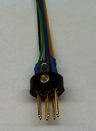
I have a piece of XLR cable connecting the 7 pin psu connector to the xlr audio output. The chassis pin is connected to pin 1 on the xlr connector. Ground is traveling over to XLR on that thick copper. The 7pin connector is grounded through pin 7 to the PCB. The Chassis is grounded to bare metal on the enclosure, through a pcb mounting pad too.
Im not sure what to try. I made sure both ends of the cable's shield is connected to the metal parts on the connectors. Im getting continuity from chassis to body of microphone...
Any ideas? Thanks!!!


Im wondering if there is something weird with my grounding scheme. Either in my mic or my PSU (hunch is psu as this didnt happen with the last psu I had).
I have a piece of XLR cable connecting the 7 pin psu connector to the xlr audio output. The chassis pin is connected to pin 1 on the xlr connector. Ground is traveling over to XLR on that thick copper. The 7pin connector is grounded through pin 7 to the PCB. The Chassis is grounded to bare metal on the enclosure, through a pcb mounting pad too.
Im not sure what to try. I made sure both ends of the cable's shield is connected to the metal parts on the connectors. Im getting continuity from chassis to body of microphone...
Any ideas? Thanks!!!
TillM
Well-known member
I used this ground scheme for my EF47 build, then all hum was gone.
https://groupdiy.com/attachments/1653742587509-png.94571/
https://groupdiy.com/attachments/1653742587509-png.94571/
Awesome. Well when I pull ground from 0v it stops all humming. What does pin 3 have to do with anything? It is not connected to anything in the microphone as far as i understand the schematic and the build. I wonder if this is dangerous to have the mic set up with out a path to earth... I wouldn't want to shock myself or any clients... It does sound great with out the hum though ;P
Ill have to get the optional switch at the shop this week.
Ground to 0v has a 50ohm resistance between the two with the unit on and 4 ohms when the unit is off... so I suppose there is a low impedance path to ground there. Kind of strange...
Ideas about safety?
Ill have to get the optional switch at the shop this week.
Ground to 0v has a 50ohm resistance between the two with the unit on and 4 ohms when the unit is off... so I suppose there is a low impedance path to ground there. Kind of strange...
Ideas about safety?
Salve, gentilmente, dove posso acquistare il PCB?Ciao GroupdiY,
Ultimamente stavo lavorando con Oliver con il suo consenso per realizzare un piccolo kit PCB per costruire la sua versione dell'U47 con tubo EF800.
Come forse già saprai, Oliver è morto, ma ho deciso di andare avanti e finirlo in sua memoria.
Questo microfono una volta terminato si chiamerà OA tribute U47.
qui alcune informazioni parziali sulla costruzione, il microfono utilizzerà Oliver Clasic serie BV08 Transformer e tubo Ef800 che mi ha inviato personalmente, ne sono onorato, non potrei mai ringraziare abbastanza Oliver.
Alimentatore
PCB
microfono
Continua.............
Migliore,
Dan,
Ciao a tutti, ho appena terminato il test finale di questo microfono, tutto funziona come previsto e sono incredibilmente contento dei suoni di questo microfono
e una delle cose più impressionanti per non dire altro questo microfono è incredibilmente silenzioso con questo tubo Telefunken Ef800 al suo interno,
Questo kit sarà in grado di pilotare tubi Telefunken Ef800, eF802 ed Ef80
Lo adoro assolutamente.
Sto aprendo il kit alla comunità fai-da-te mentre parliamo, c'è qualche aggiustamento minore che ho avuto a che fare con il valore di resistenza dell'alimentatore
ci sono note sulla distinta base del mouse condiviso su tali modifiche.
PSU PCB Silk Errata
Deve essere
H+
R2 = 6,8ohm 3W
R6 = 4,7ohm 3W
R11 = 4,7ohm 3W
SI+
R1 = 20K 2W
R3 = 20K 2W
R8 = piatto da 25K.
Questo progetto deve essere adattato a B + 105 V e H + a 5,05 V come da schema Oliver
Assicurati di seguire il numero del componente sullo schema che è pubblicato qui , non sono gli stessi dello schema di Oliver
La distinta base non contiene l'interruttore reed ma è disponibile in quelle posizioni,
il PCB è progettato per supportare questi 2 Reed Relay 24V e 48V, Solo un resistore è specificamente utilizzato sull'alimentatore per relè 24V o 48V. Le note sono anche nella distinta base, Rcoil Relay sull'alimentatore indica la resistenza per il funzionamento a 24 V o il funzionamento a 48 V.
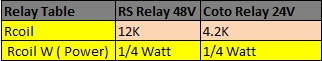
Relè Reed schermato da 48 V Disponibile nella pagina dell'ordine all'interno della casella di selezione dell'ordine D-47 o D-EF47
http://www.vintagemicrophonepcbkit.com/orders.html
Collegamento a relè 24V alternativo
http://www.digikey.ca/product-search/en?vendor=0keywords=7101-24-1010 Relè Coto PN 7101-24-1010
Ecco la scheda tecnica dei tubi per questo progetto,
https://cdn.groupbuilder.com/groupdiy/u/39511/58d1402a070fa.pdfhttps://cdn.groupbuilder.com/groupdiy/u/39511/58d1402a0710a.pdfhttps://cdn.groupbuilder.com/groupdiy/u/39511/58d1402a0711b.pdf
La serigrafia verrà corretta nel prossimo lotto, se presente,
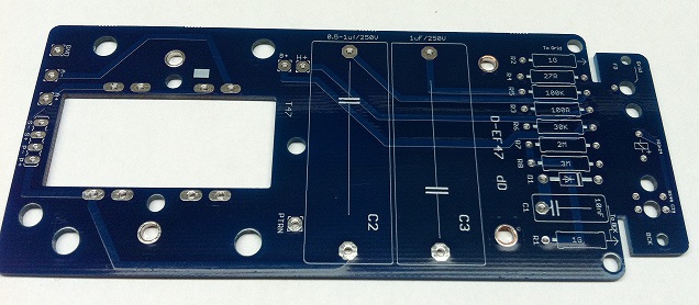
Il PCB è stato appositamente progettato per avere un pacchetto per AMI BV08 Classic Series e AMI T47 Transformer,
È possibile montare anche un altro trasformatore. Ecco le 2 strategie di montaggio che consentiranno l'uso di qualsiasi trasformatore.
https://cdn.groupbuilder.com/groupdiy/u/39511/58d1402a0712b.zip
non potrebbe essere più felice con questo giocattolo,
Grazie Oliver.
Spero che ti divertirai,
Migliore,
Dan,
Microfono Schemo
https://cdn.groupbuilder.com/groupdiy/u/39511/58d1402a0713c.pdf
Schema alimentatore
https://cdn.groupbuilder.com/groupdiy/u/39511/58d1402a0714e.pdf
Distinta base Psu
https://ca.mouser.com/ProjectManager/ProjectDetail.aspx?AccessID=acb9dba578
BOM Mic
https://ca.mouser.com/ProjectManager/ProjectDetail.aspx?AccessID=f104b8493a
Schema D-EF47 Grazie aTrans4Funk1
https://cdn.groupbuilder.com/groupdiy/u/39511/58d1402a0715f.pdf
Questo è Hoe è successo,
Migliore,
DAn,
Pittorica .
Viene mostrato il doppio tubo D47 ma il principio e la connessione sono gli stessi, basta dimenticare l'altro tubo
Migliore,
DAn,
Salve, gentilmente, dove posso acquistare il PCB?Qualche altra immagine
Grazie mille
TillM
Well-known member
Awesome. Well when I pull ground from 0v it stops all humming. What does pin 3 have to do with anything? It is not connected to anything in the microphone as far as i understand the schematic and the build. I wonder if this is dangerous to have the mic set up with out a path to earth... I wouldn't want to shock myself or any clients... It does sound great with out the hum though ;P
Ill have to get the optional switch at the shop this week.
Ground to 0v has a 50ohm resistance between the two with the unit on and 4 ohms when the unit is off... so I suppose there is a low impedance path to ground there. Kind of strange...
Ideas about safety?
I used it in all my builds and all my friends with professional recording studios who used this ground schematic are really happy with it.
Pin 3 and 7 and the ground pin on XLR should make it save.
Similar threads
- Replies
- 113
- Views
- 28K
- Replies
- 415
- Views
- 105K
- Replies
- 12
- Views
- 6K