need 12au7 WCF example

GroupDIY Audio Forum

Help Support GroupDIY Audio Forum:

This site may earn a commission from merchant affiliate links, including eBay, Amazon, and others.

rafafredd

Well-known member
Joined
Jun 3, 2004
Messages
2,409
Location
Rio, Brazil
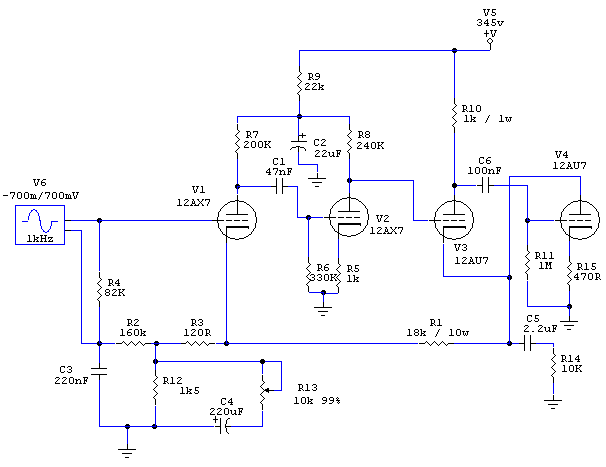
Does anyone knows where can I find a 12au7 white cathode follower example? I have draw something, but I´m sure I had seen sucha thing before. I will use it to mod my Pultec MB1 output stage.

Here is what I did:

mb1_WCF.gif


The gain control and WCF idea is from our friend IgorJazz. Thanks for this, Igor!

I´ve tried the gain control and it works nice, but I´m drawing my own WCF output because I would like to use ECC82s and he uses the hard to get 6414s.

As always, any inputs are welcome.
 
Rafael,

You image doesn't show up, for some reason.

The WCF circuit shown in the "Tube Line Amplifier" thread was originally tried with a 12AU7, before I switched to a 12BH7 for more drive capability. The circuit, as shown, will work with a 12AU7, but you should experiment with a different value of plate resistor. Use a resistor substitution box or a decade resistor in place of the plate resistor, and dial in whatever value gives you maximum undistorted output swing. If I remember correctly, something between 470 ohms and 1K worked well with the 12AU7. The 12AU7 isn't beefy enough to drive 600 ohms directly, so it'll need to work through a stepdown transformer.

Note that the grid of the upper triode needs a DC bias, a couple of volts below the voltage on its cathode. This can be provided by a resistor divider (with signal input capacitor-coupled), or you can direct-couple to the previous stage if you can arrange for the plate of that stage to sit at the correct DC level. If you use a resistive divider, try 1.1M (upper) and 1M (lower) as a starting point.

For best output drive capability, bias the follower as "rich" as possible without exceeding the plate dissipation rating of the tube. When calculating plate dissipation, remember that the voltage across each triode is not the full B+, but about half.
 
I looked around and found a schematic of the 12AU7 WCF I was using before I switched to 12BH7. Here it is:
12au7wcf.gif


The plate resistor is the approximate reciprocal of the transconductance (as recommended in the Broskie article); but one thing I found, at least in the 12BH7 version, was that I got slightly better results by using a value somewhat higher than the math had predicted. Don't be afraid to experiment.
 
> 12au7 white cathode follower

What are you driving?

If only 10K and up, 12AU7 is not the ultimate choice but very good.

If you are driving 600 ohms to Pro levels, the 12AU7 just won't do well. The plate impedance of a rich 12AU7 is about 10K-15K. Driving 600 ohms you can only get around 600/10,000= 0.06 of the supply voltage as load swing. Taking 345V supply, only half of that available on each side of the wave, we have 345V * 0.5 * 0.06 = 10V peak swing in 600 ohms, or barely +20dBm. And the gain will be well below unity, and distortion will not be as low as possible.

For 600 ohms, you want a bigger tube. Parallel 12AU7, or Dave's 12BH7. 6DJ8 looks good on paper but may have short life in this duty.

> the grid of the upper triode needs a DC bias

The value of this bias is quite critical for max symmetric swing and lowest even-order THD.

That may be part of why your result differs from Brodski's. And max symmetric swing is not the only criteria: try different load impedances, look at THD both near clipping and well below it, look for waveform balance between top and bottom (this is very load dependant). As long as the top grid is near half-way, cranking it up and trimming for max output isn't the wrong way to balance, but isn't best for all conditions or criteria.

(Brodski's analysis ignores the fact that Gm is very-variable in a power stage.)

> For best output drive capability, bias the follower as "rich" as possible without exceeding the plate dissipation rating of the tube.

For completeness: if you try that rule with very-very low supply voltages, you will run into grid current before the plate glows. That is not a problem for the usual suspects working at B+ of 250V and up, but if you work down around 100 volts (as for headphones or speakers) the zero-grid line is the limiting factor. (Unless you want to drive grid current, but that is usually wasteful when supply voltage is low, or when stage voltage gain is low.)
 
So, now I remenber where I´ve saw it. It was probably the first schem of your line amp.

Thanks for the comments. I see I was not in the wrong direction, then.

[quote author="NewYorkDave"]

You image doesn't show up, for some reason.
[/quote]

Does anybody else has problems seeing the image?

Well, the only significant difference I see is the cathode resistor. I´m using a 470R unbypassed resistor. Should I add a cap there?

The grid of the 12au7 is sitting at 119v bias from the previous 12ax7 stage, directly coupled.

I will be using a 4:1 10k600 output transformer, so I may get a low output. Maybe I should use a 3:1 or even 2:1 like in Jakobs SRPP stages...

But, I will solder it as it is right now and test it. What do I have to loose?

Here is a simulation, with a 10k load:

mb1_WCF_simulation.gif
[/quote]
 
I think you're stuck with using the 4:1 transformer. The 12AU7 will have a hard time driving anything much under 10K. PRR explained why, and my own experience on the bench confirms this.

The pain-in-the-ass is that your signal swings need to be 4 times the amplitude you require on the output. You can only swing so many volts before the output stage (and the stages preceding it) clip. But you may be able to swing enough before that happens... Outside of tedious analysis, there's only one way to find out!

Your second image isn't showing either. At any rate, simulations of tube circuits are only slightly better than useless (at least with the models I've used). Best to "simulate" it with solder instead! :green:
 
So, in the end, I´ll give away from the 12au7. I could use a 2:1 transformer on the output, but I´ll be stuck by a high impedance output, like 2k or more... And it will not drive most inputs ok.

So, I´ll change to a 12BH7 instead and use Daves circuit as it is.
It´s the same pinout, so I´ll not have to redo all my BAD point to point work. This would be a pain, because it´s really messy inside this micpre.

Guess what... my first DIY...

Thanks for the comments about the 12au7 WCF, but as I understand, this will not do it. NYD and PRR. Couldn´t be better.

Anyway, I have some 12BH7a here. And they are way more common than 6414.

Dave, do you think I should use a 1:1 600/600 transformer or a 2:1 2400/600 with your 12bh7 WCF stage? I don´t think the 10k/600 is a good choice, so I´m taking this one out to. It will be a pain!
 
The reason the WCF in my line amp circuit can drive a 600R load through a 1:1 xfmr is because the WCF is enclosed in a voltage feedback loop along with two amplifying stages. This forces the output Z to be even lower than usual, up to the point that the tube simply "runs out of steam" and can't supply more current into the load.

If your WCF is going to be more of a "standalone" that's tacked on to the output side of an existing circuit, then better to use a stepdown transformer.
 
No, it´s not standalone. It´s also inside a feedback loop in my micpre. I´m really curious to know if it will have the same behaviour (low output Z) in my circuit such as in your circuit.

Let me know if you can see the pics now. I´ve uploaded it in another place.

mb1_WCF.gif
 
Yes, C4 is backwards in the schem, but not on the unit. I´m not really sure about what I´m saying but I really think that R1 cannot be capacitor coupled...

The unit is working really nice with this schem:

mb1_gain.gif


So, I just wanna substitute the cathode follower for a white cathode follower to see if I get any improvements. That´s what´s Igor did, using the same feedbback as the original but the gain control.
 
[quote author="rafafredd"]I´m not really sure about what I´m saying but I really think that R1 cannot be capacitor coupled...[/quote]

Well, if you're not sure, then why do you think that?

Compare the two schematics carefully. In the original circuit, R1 is the path to ground for the cathode of the V3/V4 cathode follower. That's why it must be direct-coupled; if you put a cap there, the tube would be "open circuit" and it would just sit there, not conducting and passing signal.

But in the modified circuit, R15 is the cathode bias resistor, and V3/V4 should be drawing their cathode current entirely through that. If R1 is direct-coupled, then R1, R3 and R12 are shunted across V4 and V3 will draw some of its current through them, instead of entirely through V4. This will affect DC conditions in the WCF to some extent--perhaps not enough to make a big difference, but it's just poor form.

Good luck.
guinness1.gif
 
You are right. Sorry, I really didn´t meant to argue with you. I don´t even come close to have this kind of knolodge.

So, now I can´t see a way to make it a white cathode follower. Let me know if I´m wrong. I´m here to hear and learn.

Do you think it´s worth to try as it is just to listen if I like it better than the original cathode follower? Or the WCF mod I suggest is just a flawed circuit as it is and there´s no point in soldering something like this?

I was ready to solder it when I came back here. :sad:

I may add that I don´t think the origibal CF sounds bad as it is, but I would just like to listen to the Igor mods. Maybe he did it another way.

So, I´ll forget this WCF idea and use the MB1 as it is. I´m already very happy with the implemented gain control.

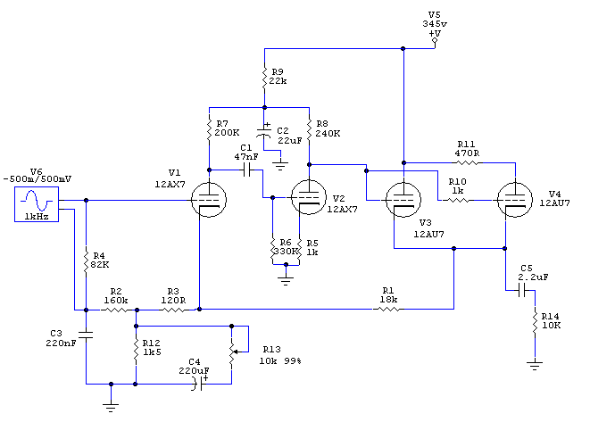
Or turn this into something totally different, if I NEED to go WCF...

mb1_WCF_2.gif


So, just let this thread die, because it ended as a "how not to wire a WCF"...
 
Back
Top