Help with distorting DBX 165 compressor (stuck thresh).

GroupDIY Audio Forum

Help Support GroupDIY Audio Forum:

This site may earn a commission from merchant affiliate links, including eBay, Amazon, and others.

Ethan

Administrator
Admin
Moderator
Joined
Jun 3, 2004
Messages
1,602
Location
DC
I have a DBX 165 that was grossly distorting. I traced the problem to the DBX202 VCA and tried replacing it with a THAT 2180LB (there were pads right under the DBX202 that were pin compatible with the THAT 2180LB pinout. Now I've got no audio.

I injected a 1k tone and traced with a scope to the input and the output pins of the THAT 2180LB and I see the wave (albeit a little jagged), but no audio gets to the output. With bypass engaged, of course audio goes through just fine--just to make sure it wasn't the input or output connectors. Voltages at all the ICs seem normal (when compared with another DBX165)

Any help would be much appreciated.
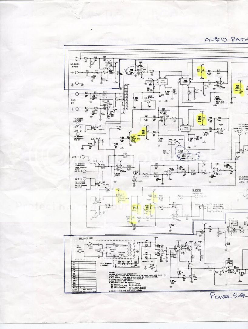
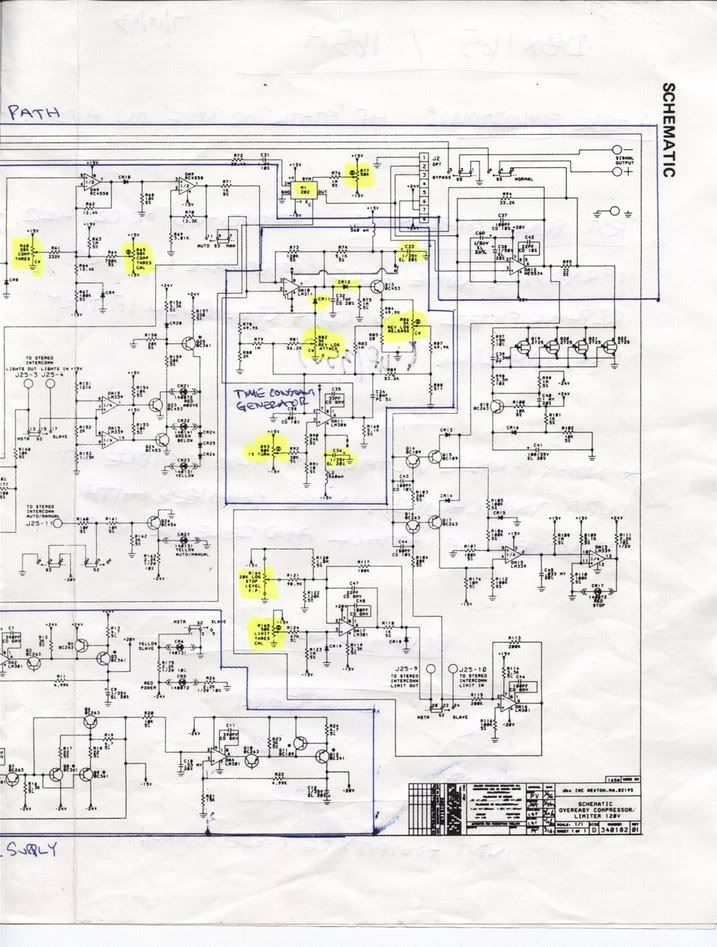
The schematic is here:
http://classes.berklee.edu/mpe/pdf_files/manuals_pdf/dbx_165a.pdf
 
I had an almost identical failure on a 165 also. Same symptoms.

In the end it turned out to be one of the parallel 'gang' of FETs (Q19-Q22) hanging across the signal output after the VCA and pulling it to ground.

I pulled all 4 FETs and replaced them one at a time until the signal died. Then I fan it with three FETs only. Worked fine until I found a similar FET, probably didn't really need all 4 anyhow.-I think it's a 'thump-stopper' mute on power up/down.

You might want to try lifting the drains of all 4 FETs, just to see...

keith
 
Hmmm... you didn't plug the 2181 into J2 did you??? -It's got +20V on pin 7 and -20V on pin 8. -I can't think of what J2 was for, but EC (voltage control for varying gain) doesn't appear to go there.

That might be why it's not working with a 2181 in there. plus the 2181 probably wouldn't like -20V getting shoved up it's butt, and its input would be tied hard to ground...

But yes, I like my diagnosis the more I think about it. The reason that they put the 4 FETs in parallel is that one FET isn;t enough to completely kill the signal. (source Z is about 33Ω through R35.) So one FET going as 'short' as it usually goes will cause the op amp to struggle like crazy. Hence the loaded & distorted signal. 4 FETs working together is enough to mute a switch-on thump and take the beast down all the way to the floor... -Like leopards working on a Thomson Gazelle! :wink:

If you did plug the 2181 into J2, then there's be no signal...

Am I right? :green:

Keith
 
Thanks Mucho Keef!
[quote author="SSLtech"]Hmmm... you didn't plug the 2181 into J2 did you??? -It's got +20V on pin 7 and -20V on pin 8. -I can't think of what J2 was for, but EC (voltage control for varying gain) doesn't appear to go there.Am I right? :green:
Keith[/quote]

Nope! :grin: I thought about it though :wink: until I realized that firstly, the pads are way too far spaced out to fit the single in line package of the 2180, and secondly, as you mentioned the +and-V among other things were wrong. Good for a test points though.

Where I stuck the 2180 is right under where the 202 used to be, the traces from the pads extend to the correct pins of where the 202 was. Input, Output, +/-15V, Ground, etc...

I'll try sticking the 202 back in there and going for the FETs.
Do you know if THAT2002 are pin compatible with the DBX202? I thought I heard that's the case.
 
2002. -Is that silver or gold? -I remember having one in an Amek M3000 but it didn't work when I replaced a 202 with it, so I have no definitive knowlege.

My money's still on a FET... I like that idea.

Keith
 
I have a silver.
I'm not really intent on using the THAT2002 in there, just curious (in case it turns out not to be the FETs). But I'm sure you're right about the FETs, you're always right (smart arse b'turd :green: )

I'll report back what I find!
Thanks!
 
Ethan,

Ive got a bunch of those 202 VCAs if that what you end up needing.

http://www.groupdiy.com/index.php?topic=10344

Helsing
 
I agree completely with SSLtech's diagnosis. I have seen a good number of dbx comps with the muting FET's shorted - seems pretty common. They all seem to have shitty power cords too. Sometimes I get them with all of the FET's missing and it causes a strange noise on power up/down if I remember correctly. I recently happened on a unit with factory installed 2N4392 FET's in it. This was exciting for me (sad, huh?) because the schematic appears to use a house number and I was never ambitious enough to figure out what they were. Mouser has the 2N4392's.

To get the best noise and distortion figures you will need to change the input and output resistors before and after the VCA. I think that the newer VCA's generally require smaller resistors than the older black cans did. I'm not sure about the differences between the 165 and 165A, but I was just doing this very thing today with a 165A and a new modular VCA. The input resistor needed to be changed to a 3K57 and the output needed to be 5K7 (not standard, of course) to give me unity through the unit. Since you are using a single VCA your values will be different. If you don't change them it's not the end of the world... I have a schemo for the 165A and some notes about problems I've encountered with them. If you are interested let me know. I'm looking for a parts layout if anyone has one.

Tim
 
Thanks Helsing,
I'll let you know in a few days if I will need some (if they are still available then?)

Tim,
Thanks for the info.
I have a schemo for the 165A and some notes about problems I've encountered with them. If you are interested let me know.
Any info would be fantastic.

Thanks!
 
OK so I put the DBX VCA back in there and I'm not getting output. According to the meter, it's getting input and compression is working and responding to all controls, just no output signal.

I found that I'm not getting -20V at J2-8. I'm getting around +1.7V. I've followed the traces back to this area (picture below, the red is what I have). I thought maybe Q12 was the culprit but I replaced it with no luck. Any advise would be greatly appreciated!

dbx-voltages.jpg
 
another common problem (at least for me) with those dbx cans are the pins comming loose inside the can. try resolder them and everything else
 
If you mean the DBX VCA, I can see input and output from the VCA with a scope. I just don't get any signal at the XLR output. Bypass works just fine so it can't be the actual output connector.

The +/- 15V for the VCA are also fine. It's at the 5534 opamp that's fed by the output of the VCA where I'm not seeing -20v
 
I did, or at least I've been trying. That's what the above picture is. Where it looks like the -20V is supposed to "start" that ends up giving -20V power to the ne5534 at the output.

EDIT: on second thought, that doesn't look like where the -20V starts, but I can't seem to find any other place that looks like -20 is given. I've checked at the power supply and I do have the main +24 and -24 (actually +/- 29V which seems reasonably in range).
 
Ethan,

You shouldn't measure ANYTHING at the VCA output. It's a current output device, and it dumps current directly into the inverting input of the op-amp follower.

A general working rule is that an op-amp working stably should modulate its output voltage to maintain the two inputs at the same potential as each other. If the non-inverting input pin is grounded, then the inverting input becomes a virtual ground. (for non-inverting operation, tying the output to the inverting input and feeding the signal in to the non-inverting input forces the op-amp to make it's output match its input, a simple impedance conversion is a handy benefit of this one-component trickery, but I digress...)

For example, If the output of the op-amp is pulled to ground, it can't swing around to send the opposing current (the output voltage fed through the negative feedback resistor -in this case R34) back to the inverting input summing node.

If you're reading voltage at the inverting input, there's probably not enough negative feedback. A shorted FET or other type of hard short will do exactly this for you. -So will an open-circuit R35 by the way, since feedback is taken after it. Also, a dead 5534 will do it.

From what you measure, there's signal of some sort going in to the 5534. All you need is a working op-amp and effective negative feedback to make magic happen. If you're missing a voltage at pin 7 or pin 4 of the chip, that might be an issue, otherwise, it's all fairly doable.

Keith
 
Thanks guys.

[quote author="SSLtech"]If you're missing a voltage at pin 7 or pin 4 of the chip, that might be an issue, otherwise, it's all fairly doable.
Keith[/quote]

That is actually the most blatant problem currently. I'm not seeing -20V at pin 4 of that 5534. I can't seem to find where the -20V "begins". :sad:

I'm not sure if this would make a difference but I pulled out two of the 4 paralleled FETs, Q20, and Q22
 
Sorry it took me so long to get this up, but I have been out of town for a few days.

About the extent of my notes on the 165 are the symptom of a high frequency "buzzy" sound mixed with the audio. It turned out that C33 and C34 had increased in ESR and they were not filtering the HF crap from the time constant generator section. The first unit I had with this problem had tants in these positions, this surprised me. By the way, I can't remember how I came up with the names for the sections of the circuit that I have drawn in there. I must have guessed. I hope this helps!

Here is the 165 schematic as two scans because it was large:

165Schem1.jpg


165Schem2.jpg
 
You should not see any voltage on the DbX VCA In and Out pins. These are current-mode, not voltage mode.

-20V comes from Q10 Q11 Q12.

+/-24V are unregulated and +/-27V is not unlikely. The +/-15V and +/-20V are regulated and must be very close to nominal.

Do you have monster signal on one side of R95 and no signal at the other side? Take ALL the JFETs out.

If no signal and in doubt about the VCA, remove it and jumper In to Out. This is the equivalent of a VCA stuck at unity gain, and will prove the rest of the signal path.
 
After replacing Q10, my voltages at the power pins of the 5534's are back to normal and now I'm back to the original state of low and distorted output. I pulled all the JFETs still no joy. I'll poke around a bit more with the above suggestions and report back.

In the process I have been noting all the transistor numbers that DBX conveniently renumbered on the schematic so I will post an annotated schematic when I finally get this thing back up and running.
Thanks mucho!
 
[quote author="Ethan"]After replacing Q3, my voltages at the power pins of the 5534's are back to normal and now I'm back to the original state of low and distorted output. ..[/quote]

Hi,

I experienced a great deal of trouble with dirty switches on several 166s and 160s. Check the master-slave switch first. Also, try setting the master-slave switch in the slave position and connecting the stereo ctrl in to the ground. VCA's gain should be OdB. If the signal doesn't appear at the output, I'd say that the VCA is dead.
BTW, I'm sort of baffled as to how transistors Q3, Q7 and Q10 work...

Regards,
Milan
 

Latest posts

Back
Top