Hi Ray,
I?ve also got some 101?s on order.
Below is all the information I have gathered while doing my own research.
Most of it was gained from posts from the VERY knowledgeable Fred Forssell, who
knows ALOT about these pres and hopefully will jump in with further info.
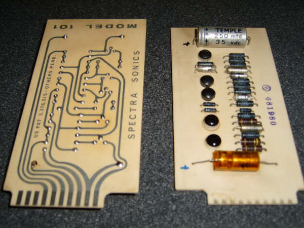
The 101?s is a single ended +24VDC pre card, later replaced with the 110,
which is a Bi-polar Pre design (using a +24VDC/-24VDC configuration) and
inherently the 110 has a bit more headroom. The 101 was used all over the
Spectra Sonics desk in various rolls, including the famous 610 compressor.
For me it seems the 101 is to Spectra Sonics what the BA283AV is to Neve.
The pin out configuration on the 101, to my knowledge is as follows:
Pins 1,2,3 = Not Connected
Pin 4 = Input (+)
Pin 5 = Input (-)
Pin 6 = Ground
Pin 7 = Output (+)
Pin 8 = +24V
Pin 9 = Feedback out
Pin 10 = Feedback point for gain set resistor (feedback return)
You are correct in saying that it can be ?temperamental? with the gain
staging.
Fred words were:
I think you can get a limited adjustment range before the amp becomes unstable. From memory, it's pretty touchy.
The gain set resistor is connected between pins 9 and 10. The
following resistance values were give by Fred for the 110 cards, I?m not
sure how they differ from the 101, if at all.
40 dB gain Rf= 10.7k
45 dB gain Rf = 20k
50 dB gain Rf = 42.2k
The Input impedance of the 110 card is FIXED at 600 ohms (it's a grounded
base input amplifier) and the feedback return impedance is 100 ohms.
The cards originally used the Triad A-67j transformers as input transformers
and the HS (forget the model no) on output.
I would like to know how to add a pot for better gain control, this I?m
still not sure of, amongst a few other things.
Hopefully someone with more knowledge can assist you (and I) with these
questions and confirm the pin-outs.
Cheers
Matt


")