two transformers as one - series/parallel

GroupDIY Audio Forum

Help Support GroupDIY Audio Forum:

This site may earn a commission from merchant affiliate links, including eBay, Amazon, and others.

rafafredd

Well-known member
Joined
Jun 3, 2004
Messages
2,409
Location
Rio, Brazil
So, I have two 20dBm 3:1 output transformers...

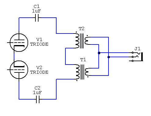
For higher signal handling and higher ratio, would it be possible to wire it like this:
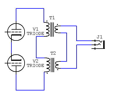
parallel_series_trafos.gif


Will both transformers work as a one 6:1 transformer? Any problems in doing this?

I know that I´ll have to add coupling caps because the trafos are not gapped and they are not working in real PP operation thus not canceling DC...

But it´s just a representation drawing, you know...
 
I can't see any specific problems with the general idea and I have used this a number of times. See the Tubed EQ at the old place.

You can juggle the trafos to create some variations in ratios and if you are clever you may even get some humbucking going on depending on how you arrange things. Some may disagree with the word I chose to use there.

Back to the point,
you said the trafos were 3:1 and when combined they are 6:1 ... :roll: ... I don't see that with the above drawing ??
I think I see 6:2 ... :? ... 3:1
 
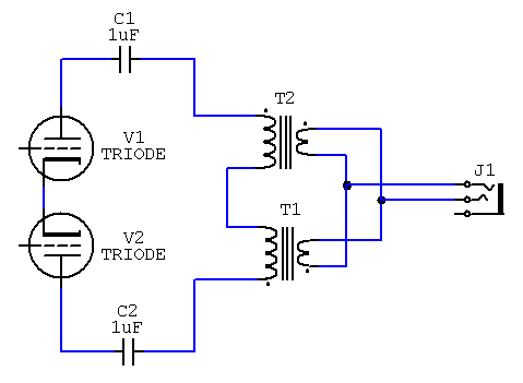
Oh, yeah Kev... just lack of attention. Off coarse I meant to wire the secondaries in parallel...

I´ll just update the pic.

If you can say something more about the "humbucking" method of arranging the windings, this would be cool. :thumb:
 
The way you have drawn it, it will still be 3:1.

Wire the primaries as you have drawn, but connect the secondaries in parallel. Also, these had better be gapped xfmrs if you plan to draw DC plate current through them, as you seem to be implying in your drawing. The junction where the two primaries are joined is where your B+ connects; or, if it's a shunt-fed application, it would be grounded.
 
If you fed B+ to the two tubes from a center-tapped choke, or two matched chokes, rather than via the "center tap" where the two transformer primaries are joined, you would have a plate-to-plate single-ended amp similar to the output stage of this:

http://www.electra-print.com/ppse_2.html

Just throwing it out there.
 
Yep, and don't forget to ground your primary "centertap."

The plate-to-plate load impedance (including the parallel resistance of whatever plate resistors you use to feed B+ to the tubes) should be at least twice the plate resistance of each tube, or you'll get a lot of distortion. Even with a 6:1 turns ratio (36x impedance ratio), you'll need tubes with a rather low plate resistance to pull this off. The 12AU7, 12BH7 and 12AV7 are potential candidates depending on the output level required. This scheme will work best with high B+, since that'll allow you to use a larger value of plate resistors and minimize the shunting of the transformer primary.
 
A "single-ended push-pull amplifier?" :?

Leave it to the audiophiles!

They can call it what they want, but single-ended and push-pull are mutually exclusive. Don't be fooled by the fancy business with the tapped chokes; it's just a p-p amp.
 
If this is a push-pull output, then your second picture has the transformers wired in wrong phase. (Wait and see if NYD corrects me on this... I may just be confused.)

I don't see any hum-bucking worth considering. This is a push-pull output stage where levels will be MUCH higher than induced hum. The only way hum should be a problem is if you are too-too-close to a power transformer, and in the near-field of a power transformer there probably isn't much cancellation possible. Distance is usually cheaper than sheilding or cancelling. And output transformers almost never suck enough hum to hear.
 
[quote author="rafafredd"]If you can say something more about the "humbucking" method of arranging the windings, this would be cool.[/quote]
:roll:
mmmm
Get your diagram worked out as PRR has suggested ... by the time people read all this it may be all squared away.

Then get a couple of trafos and then hold them in your hands and have a good think about magnetic fields and directions of flux and stuff.

It may all just become obvious. :wink:
 
[quote author="NewYorkDave"]A "single-ended push-pull amplifier?" :?

Leave it to the audiophiles!

They can call it what they want, but single-ended and push-pull are mutually exclusive. Don't be fooled by the fancy business with the tapped chokes; it's just a p-p amp.[/quote]

Single-ended push pull is another name for SRPP, bootstrap follower, totem pole amp:

http://www.tubecad.com/articles_2002/SRPP_Deconstructed/index.html

Whether it's more se or pp is up for debate.

As for the plate-to-plate amp, I agree that it's more push-pull than anything because it has a phase splitter and an output transformer where the previously split signal meet up again. Calling it plate to plate single ended is semantic tapdancing. Whether it sounds any different than an ordinary pp amp, I'd have to build the damn thing to find out. Not going to happen for a couple of years at least.
 
So, here is the last and the only working version:

series_parallel_trafos_2.gif


[quote author="Kev"]Then get a couple of trafos and then hold them in your hands and have a good think about magnetic fields and directions of flux and stuff.
[/quote]

I think I know what you mean, Kev... I should arrange the flux in the same direction,no?
 
Where do you have the B+ and ground? Norman Crowherst did some output transformer combining in the 1950's I think. I may have an article on it and will post if I can dig it out.
 
[quote author="thomasholley"]Where do you have the B+ and ground?[/quote]

It´s only a representation, not a full schem.

Norman Crowherst did some output transformer combining in the 1950's I think. I may have an article on it and will post if I can dig it out.

It would be nice if you can do it. Would really like to read about it.
 
I think it is fine to leave the link as it is.
It's shorter than one line so doesn't get too confusing.

It also allows people to see the link string and is also printed ... if you say HERE and you print the page ... where is here ??


It also allows you to back track and get :
http://users.adelphia.net/~thomasholley/
and
http://users.adelphia.net/~thomasholley/Home.htm

ooo ! :shock: look he has a :

Modified G7 Microphone
Modified V76
Vacuum Tube Synth

look in the guitar section and you will find the 48 volt miniature Tube DI schem

There is always more to people than just a link. Thomas has an older brother and although I didn't know him, I think I too miss him as he sounds like he was a fine fellow. I also miss my sister.
 
How are the grids being driven, in phase with each other or inverted 180 degrees? This will dictate how the transformers need to be connected. Also I am not sure if it is a good idea to directly parallel the secondaries, unless everything is perfectly matched there might be some "push - drag" taking place.
 
good point bill.

I don´t think those are perfectly mached trannies. Anyway, maybe they are close enought for this. DCR is very close.
 

Latest posts

Back
Top