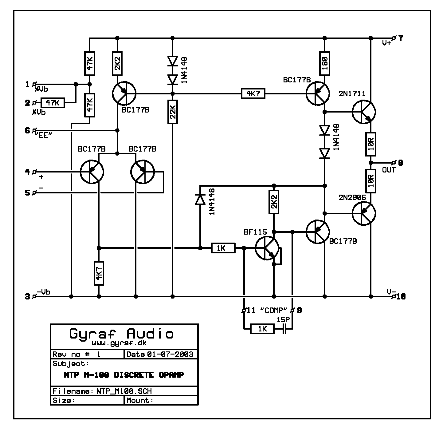
Has anyone built an M100 NTP op-amp?

GroupDIY Audio Forum

Help Support GroupDIY Audio Forum:

This site may earn a commission from merchant affiliate links, including eBay, Amazon, and others.

strangeandbouncy

Well-known member
Joined
Aug 8, 2004
Messages
2,112
Location
West Sussex. UK
Hi guys,

Hope you are all flourishing! I have recently used an NTP eq, and a limiter using the M100, and was very taken with the sound. I was looking at the schemo on Gyraf's website, and wondering how "do-able" it is. My thought was to try to build it on a 990/2520 footprint, so I can try it in my existing stuff. But I am seriously out of my depth, with no ideahow to proceed! I guess that the input transistors would need to be matched(?)
I would also very much appreciate some kind of explaination as to how the circuit works, if at all possible. To start with, do they run in class B?

As ever, i am deeply greatful for any postings on this.

All the best,

ANdyP
 
Thanks, Jakko,

Very helpful!

ANdy
 
Yeah, I did a two channel 2U rackspace transformer in / transformer out $50 mic pre based on the NTP M100. I use it all the time. It sounds nice!

Now I got a pair of NTP M100 originals here that I´ll try sometime in the next decade.
 
Please,

Could someone in-the-know (PRR? Please?) take a look at the M100 schematic and suggest

1- How it works (If I missed something..)
2- Which transistors should preferably be matched - on what parameters?
3- Common, modern-day subs for the silicon?

NTP_M100_OPAMP.GIF


Alternative schematic:

http://www.gyraf.dk/schematics/NTP_M100_Schematics.pdf

Data sheet:
http://www.gyraf.dk/schematics/NTP_M-100_datasheet_p1.jpg
http://www.gyraf.dk/schematics/NTP_M-100_datasheet_p2.jpg

Specs:
Supply voltage to +/-18V
Max. output power: 1Watt
Output voltage swing: +/-10V into 100 Ohms
Current consumption ~6.5mA

Open loop gain 90dB
CMRR 70dB
Slewrate 20V/uS
Input offset voltage <10mV
Input bias current <1uA
Input offset current <0.1uA
Input impedance 30KOhm

Jakob E.

(Moving this to the Drawing board..)
 
I'm neither Paul nor am I sure why you shouldn't understand this opamp better than I do, but give me a try...

1- How it works (If I missed something..)
The first two BC177B form the differential input pair. Standing current is set by a current source and hopefully balanced by the resistive collector load (the 4k7).

The BF115 is the voltage amplifier stage which is buffered by an emitter follower (another BC177B). These two stages share one common current source. The standing current seems to be distributed by the 1N4148 diode and the 2k2 resistor.

The output stage is standard and doesn't need further explanation.

2- Which transistors should preferably be matched - on what parameters?
Input pair for beta and Vbe for best DC precision, but probably pointless as there will be high drift anyway.

Output pair for beta if you intend to drive heavy loads with low distortion--likely to be pointless as well as there are more dominant sources of nonlinearity in this design.

3- Common, modern-day subs for the silicon?
BC177B -> 2N4403/BC560C (perhaps 2SA970BL for the input pair)
BF115 -> MPSA18
2N1711 -> MJE180/BD139/FPN560
2N2905 -> MJE170/BD140/FPN660

Perhaps someone could recommend a TO-39 pair for the output? The TO-126s are a bit slower than the original ones.

Next time you name the components, OK? :?

Samuel
 
I only matched the input pair for beta.

Mine has a very low DC offset, and I load it with a 150ohms transformer, with no caps, and it works nice. Not a transparent preamp, but definetly a nice one, specially for that price.
 
I used a 2SA798, low noise/high gain dual transistor, for the input pair on my prototype. It is not that common part, but there is lots of surplus stock of them.
 
Dear All,

Thank you all so much for your response on this. Especial thanks to Samuel for his most illuminating explaination! I guess that it is "do-able", ney, "Done". I shall start to gather up the necessaries right away. I'll let you know how I get on.

All the best,

ANdyP
 
What Samuel said.

It is an ordinary op-amp. Just for reference: if you look at Jensen 990, this is upside-down and the middle emitter follower moved over one place. It lacks some detailing of the 990; whether that matters or not depends on what you are doing.

I don't see why it would have "a sound". If ANdyP liked the box, it may have been due to other factors than these amps.

The resistors on pins 1 and 2 are convenient for single-supply work, probably useless in dual-supply work.

Short-protection is skimpy. I daresay the 2N2905 or its driver could be killed with a dead short and a strong signal.

If you don't need 100-ohm drive, I'd build it with PN2222-class jelly-bean transistors. Input device matching is nearly pointless, as Samuel points out, since it is sure to have a little offset and drift. In most audio work, this is meaningless. None of the rest needs any matching. Nothing seems very critical of parameters, though input bias current is high so use high-Beta transistors at the input.

Or use selected NE5534, or that new 603(?), or for high-class work, 990-like modules. It really is just another good audio opamp. The differences between these choices will be, for most work, pretty darn small.
 
Thanks, Samuel and Paul!

Nothing strange here, I see. The reason I ask is that these beasts are generally used in equipment that certainly has "that sound" - though it might just be that they're well designed overall, and always uses first-class in/out iron.

Do you have any comments on the differences to the "B"-version, pictured in:

http://www.gyraf.dk/schematics/NTP_M100_Schematics.pdf

..?

Jakob E.
 
Dear All,

Thank you PRR and Gyraffor your further comments. I note with great interest your comments about "that sound" being possibly more to do with the general quality of circuit design, and the effect of input/output iron. You have hit ther nail on the head for me, since this is the area \i am wanting to explore further. When working on Neve broadcast boards with a mixture of all discrete amps, and hybrid 5534/discrete output amps, I started hearing subtle, but significant differences. Both kinds sound very "Neve-ey", no doubt due to the topology/design, and especially the iron. But, there was a great improvement for me, with discrete in mic-amp, hf of eq, lf of eq, and a graet improvement with hybrid ones in mf of eq, and summing amps. Just my personal opinion! Also, I have a few bits of API stuff, 525, 553, 559, and I used to have 554's, all of which sound very "API-ey", yet have a mixture of API 2520 of many different vintages, APSI op-amps(sadly dead and buried), 2521 API hybrids, with 5534 and disctrete output. They all sound different to me! I am intreagued as to what further differences/similarities are possible using other op-amps. I have also tried Forssell 992/ Hardy 990/ Melcor 1731 to name but a few, and am merely looking for others to try! I am also intreaqued to explore the whole Class A. Class AB, CLass B thang, and was amazed to find that the NTP is CLass B! This reallly rubs against the grain for me, since I grew up in the "Class A must be better" school of thought. Just goes to show how much there is to learn . . . I am very keen to try JLM Audio's new Hybrids, made so that a moron like me can vary the bias from Class A/B thru to Class A. I know that it is not rocket science to many of you, but it means I can start somewhere, and draw some of my own conclusions, even if they are liable to short-comings! In my book, any differences, no matter how subtle, can be exploited in the mix, and after all, that's where it is at for me!

Bless you all, I really am very greatful for your time and trouble.

All the best,

ANdyP
 
Do you have any comments on the differences to the "B"-version?
The function of the two additional transistors is not clear to me--one seems to be some sort of a very rudimentary Vbe-multiplier and the other an output clamp/protection.

And I was amazed to find that the NTP is Class B!
I've seen them writing that in the datasheet as well, but I believe that nowadays we rather would call that an class A or AB output stage. It's hard to tell what the quiescent current is without simulation/breadboarding, but I would guess for something well above 5 mA which makes a good class A swing into medium impedances.

Samuel
 
Hi, the current consumtion with no signal is around 6,5 mA.
The answer from them in the 70´s was that to make a short circuit
protection builded within the "B" version. As it recommends in the earlyer
version is to put a 22ohms resistor in series with the output.
I cant tell any sonic differences between A/B/C versions
My experience is that it´s well sounding ,quiter than the 5534 with
1 kohms inputimp,when pin 5 & 6 are shorted. Some unsymmetrical clipping can be result of that,but it get´s very unnoisy!
Its a little fragile. You have to beware to load it to much. And it can
be a bit nervous and oscillate if its breadboarded to wild.
Cheers Bo
 
> amazed to find that the NTP is CLass B!

Well.....

> It's hard to tell what the quiescent current is...

Agree. In fact I don't think the drawing we have for the -B version can possibly be correct: the Vbe multiplier seems to divide by zero and give an infinite bias voltage. If breadboards have been smoking, add the missing resistor.

There is another way to estimate the output stage current. All but the output stage run at fixed current. Adding up the known currents, I get 4.0mA to 4.4mA. Jakob and Bo both say:

> Current consumption ~6.5mA

If true, then the output stage runs 1.0mA to 1.5mA.

Taking the round number "1mA", then it can swing up to 2mA peak while staying Class A. If we assume 10V peak swing, then the minimum loading for Class A is 10V/2mA= 5K. So in boards full of 10K pots and mix networks, it may run Class A for almost all conditions.

For heavy loading, the current will go much higher, to ~17mA for 600Ω loads. If you define "degree of Class B" as the ratio of peak to idle current, this is "17". (Pure Class A is "2", loudspeaker amps often run "100".) The output impedance for each emitter (at least at high frequencies where the internal feedback is working) is about 26Ω at idle, going to below 2Ω on peaks. Adding the 10Ω resistors, the overall series resistance is about 18Ω idle, about 12Ω on peaks. (For the -B it is 15Ω going to 6Ω.) On paper, crossover distortion number is less if the resistors are raised to 17Ω-26Ω while staying at 1.0-1.5mA, or if idle current is raised to 2.6mA -A, 5mA for -B revision.

Note that even at 1mA idle and 600Ω loading, it will pass 0dBm while staying Class A. So 98% of the program is in the A range, and the peaks that go into class B may be too short to hear the kink.

> quieter than the 5534 with 1 kohms inputimp, when pin 5 & 6 are shorted

Ah, yes. Convert a differential input to a single-ended input, a classic way to lose one noise source. The inverting input becomes low-impedance, but you probably needed a low-Z gain-set network anyway. The DC offset changes from ~20mV to 600mV, so you have to allow for significant DC and usually must roll off subsonic gain to unity. These changes may be acceptable in return for the lower noise. One of the variant "990"s does this (though with FET).
 
Dear PRR,

Thanks for that. Wonderful stuff! Most illuminating indeed. You have explained a plethora of things at the same time for me. I didn't understand that there was a transition from Class A to B! DOH! Makes sense now.


Cheers! :green:


ANdyP
 
I have a growing pile of dead M100's. About half of them are labeled "M100 C". Does anyone have an idea of what this version contains? I'm not sure if it keeps them from going south.

A few years ago I could swear I had an unpotted M100... but I can't find it. All of the dead M100's I have now are potted. I'd love to know what fails in these things.
 
Hello

This is an old topic but I've just depotted a M100C.

You should take the M100B schematics as a basis. The differences/corrections are :
- As PRR stated in another topic, the 3.6k resistor is not across C-E junction but should be installed between B-C.
- There is a BF115, actually in the M100C I've found a BF495.
- There is a BC237 with its collector tied to pin 9 on the schematics. Actually on M100C it is connected to pin 11.
- Two protection diodes are added, one between output and supply rail (pin 7) and the other between output and 0V (pin 10)

Hope it helps
 
Do you mean the collector (not emitter) of BC237,  because that is what I see connected to pin 9 on the schematic ?


psych60s said:
You should take the M100B schematics as a basis. The differences/corrections are :
- There is a BC237 with its emitter tied to pin 9 on the schematics. Actually on M100C it is connected to pin 11.

Hope it helps


Latest posts

Back
Top